


11
307–760
REPAIR
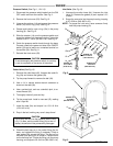
Pressure
Switch
(See Fig 1
1, 12 & 13)
1.
Disconnect the pressure switch leads from the ON/
OFF
switch and from the rectifier
. See Fig 1
1.
2.
Remove the front cover (23). See Fig 13.
3.
Unscrew the retainer (14) and remove the pressure
switch (12) and o–ring (12a). See Fig 12.
4.
Grease and install a new o–ring (12a) in the pump
housing
(9). See Fig 12.
5.
Slide the retainer (14) over the pressure switch and
screw
the retainer into the pump housing. T
orque the
retainer
to 6.2–7.4 N.m (55–65 in–lb). See Fig 12.
6.
Guide the pressure switch leads through the base.
Connect
a lead to the power–out side of the ON/OFF
switch (34) and a lead to an unmarked terminal on
the
rectifier (39). See Fig 1
1.
7.
Reinstall the front cover (23).
CAUTION
To
avoid damaging the pressure switch, do not
drop
it,
and do not press on the center of the switch.
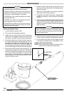
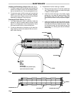
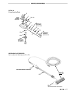
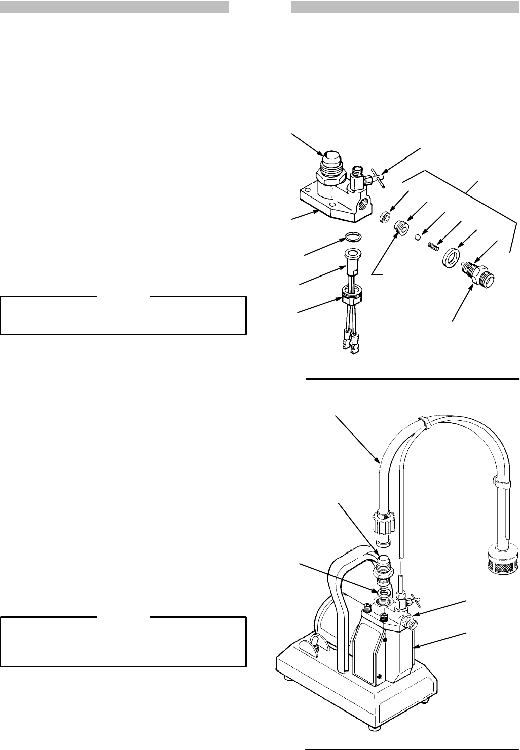
Outlet V
alve
(See Fig 12)
1.
Remove
the
outlet hose (64). Unscrew the outlet fit
-
ting
(2a) and remove the gasket (2b).
2. T
ip the pump forward to remove the ball (2d).
3.
Use a 1/4 in. square socket wrench extension to
screw
out the seat (2e).
4.
Use a pointed tool, such as a dentist’s pick, to re-
move
the seal (2f).
5.
Thoroughly clean all parts and dry
.
6.
Tip the pump back. Install a new seal (2f), making
sure
it lays flat.
7. Install the seat (2e) and torque it to 13.5–16 N.m
(120–140
in–lb).
8.
Drop in the ball, making very sure it stays there!
CAUTION
Do
not drop the ball into the pressure switch cavity
(12). If it does, and the outlet fitting (2a) is then in-
stalled,
the switch will be permanently damaged.
9.
Check the ball stop pin in the outlet fitting (2a) for
wear, and replace the fitting if necessary. Place a
new gasket (2b) around the fitting. The last coil on
one
end of
the spring (2c) is turned in. Place this end
on the ball stop pin. Screw the fitting into the pump
housing,
and torque to 32–34 N.m (280–300 in–lb).
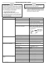
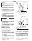
Inlet V
alve
(See Fig 13)
1.
Unscrew the suction hose (44). Unscrew the inlet
valve (3). Remove the gasket (4) and replace it if it
is
worn.
2.
Screw
the new valve into the pump housing, torquing
to
27–29 N.m (240–260 in–lb).
NOTE: To torque the inlet valve, have someone firmly
hold
the pump housing (9).
2f
Fig 12
Fig 13
10
2e
2d
2c
2b
2a
2
3
9
12a
12
14
TORQUE
T
O
13.5– 16 N.m
(120–140 in-lb.)
TORQUE TO
32–34 N.m
(280–300 in-lb.)
TORQUE TO
6.2–7.4 N.m
(55–65 in-lb.)
44
9
23
4
3
TORQUE TO
27–29 N.m
(240–260 in-lb.)