


9
307–760
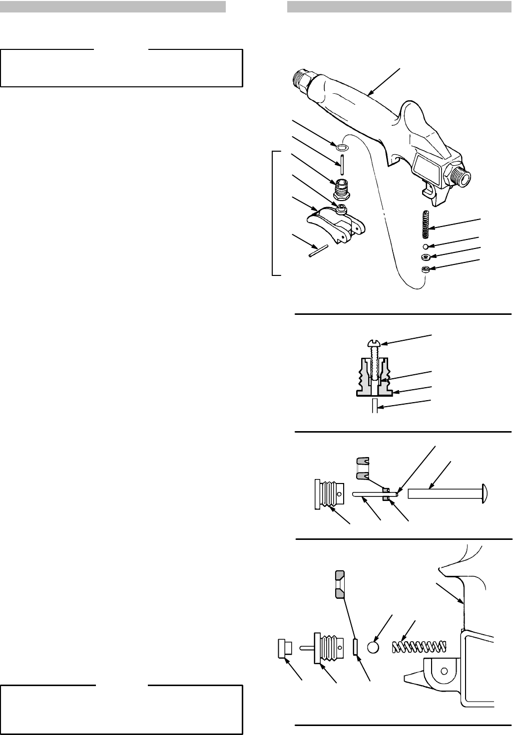
REPAIR
Roller
V
alve
WARNING
Always follow the Pressure Relief Procedure
Warning
on page 8 before attempting any repair
.
NOTE:
Order repair kit no. 218–960 to repair this roller
valve.
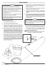
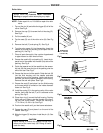
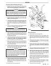
1. Tap
out the pin (A) and slide the trigger (B) of
f of the
valve.
See Fig 6.
2.
Remove the cap (C).Unscrew the fluid housing (D).
See
Fig 6.
3.
Pull the needle (K) out.
4. Tap the seat (G) out of the roller valve (N). See Fig
6.
5. Remove
the ball (F) and spring (E). See Fig 6.
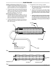
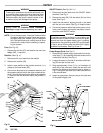
6. Turn
the nylon screw (L)
into the packing. Insert the
needle
(K) through the housing (D) and push out the
packing
(H). See Fig 7.
7. Clean
all parts thoroughly
. Use a cotton–tipped swab
or
pipe cleaner to clean small orifices.
8. Grease
the needle (K) and packing (H). Insert the ta
-
pered
end of the needle into the back (flat) side of the
packing.
See Fig 8.
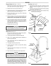
9. Guide
the tapered end of the needle into the assem
-
bly
tool (M) and press
the lips of the packing over the
end
of the tool. See Fig 8.
10.
Grease
the free end of the needle. Guide the tool (M)
into the fluid housing until the needle protrudes
through the top of the housing. Lightly tap the tool
end
until you hear the packing bottom in the
housing.
Remove
the tool with pliers. See Fig 8.
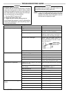
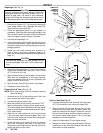
11. Grease
the seat (G) and place it on the fluid housing
so the seat which is formed on the inside diameter
faces
out. See Fig 9.
12. Install
the spring (E) in the spring cavity of the valve
handle,
then install the ball (F) so it is centered on the
spring.
See Fig 6.
13. Place
the o-ring (J)
around the fluid housing. Pushing
lightly
with your fingers, start the threads of the
hous
-
ing into the valve handle. Torque the housing to
1.7–2.2
N.m (15–20 in–lb). See Fig 6.
14.
Push on the needle until you feel some resistance.
15. Grease the cap (C) and place it on the end of the
needle.
See Fig 6.
16. Slide
the trigger (D)
into place. Install the pin (A). See
Fig
6.
CAUTION
Never attempt to remove the adapter fittings from
either end of the valve body (N). Doing so could
crack
the body
.
Fig 6
Fig 7
Fig 8
Fig 9
L
H
D
K
TAPERED
END
M
D HK
LIPS F
ACE OUT
OF HOUSING (D)
GDC
F
E
N
SEA
T MUST
F
ACE BALL
N
E
F
G
H
J
K
D
C
B
A
TORQUE TO
1.7 – 2.2 N.m
(15–20 in-lb)