


13
307–760
REPAIR
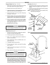
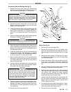
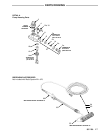
Connecting Rod and Bearing (See Fig 16)
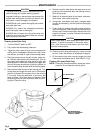
1.
Remove the front cover plate (23). Remove the
screws (15) and tip the pump housing (9) out of the
way.
Unscrew the diaphragm (17) and discard.
CAUTION
Replace the diaphragm (17) whenever you remove
the
pump housing (9). During use, small grooves are
formed in the diaphragm which cannot be realigned
properly. Reusing a diaphragm may cause leaking
which
will result in costly damage to the pump.
2.
Remove the motor screws (20). Lift the motor (30)
slightly. Holding the connecting rod, pull the motor
away
from the housing (22).
3.
Inspect the bearing (18b) in the connecting rod (18).
If it is worn or any rollers are broken, replace the
bearing
and rod assembly
(18). Inspect the motor ec
-
centric (F), and replace the motor if the eccentric is
worn.
4.
Use
your fingers to pack high–quality bearing grease
thoroughly
in between the bearing rollers.
CAUTION
Thorough
greasing of the
bearing is essential to ex
tend
the life of the bearing and
the motor eccentric.
5.
Use
a soft
brass or nylon bristle brush to clean the top
of
the
connecting rod and housing. Gently clean the
bottom
of the pump housing (9), avoiding damage to
the
diaphragm grooves.
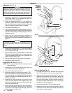
6.
Install
the connecting rod (18) in the connecting
rod
housing (22). Screw a new diaphragm (17) into the
rod
just
until it bottoms. T
urn the diaphragm
only
1/4
to
1/2 turn more (2.7–3.6 N.m [6–8 in–lb]).
7.
Align the motor with the pins in the connecting rod
housing
(22), guiding the motor eccentric through the
connecting
rod bearing (18b). Spin the motor shaft to
be
sure it moves freely
.
8.
Loosely
install the lockwashers (21)
and screws (20).
Spin the motor shaft again. Now alternately tighten
the
screws. Spin the motor shaft again.
CAUTION
Spinning the motor shaft while assembling the
pump
ensures that parts
are properly aligned. If they
are not, and you start the pump, serious damage
could result to the motor, bearing, and connecting
rod. If you feel binding or resistance, disassemble
the parts, checking the spin often, until you deter-
mine
the cause of the binding.
9.
Position
the pump housing (9) on
the sprayer
. Lubri
-
cate the screws (15) and install them and the Iock-
washers
(16) loosely
. T
orque the screws a few
inch–
pounds
(N.m) at a time, oppositely and evenly
, to
85
in–lb
(9.8 N.m).
10.
Reinstall the front cover plate (23).
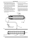
30
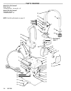
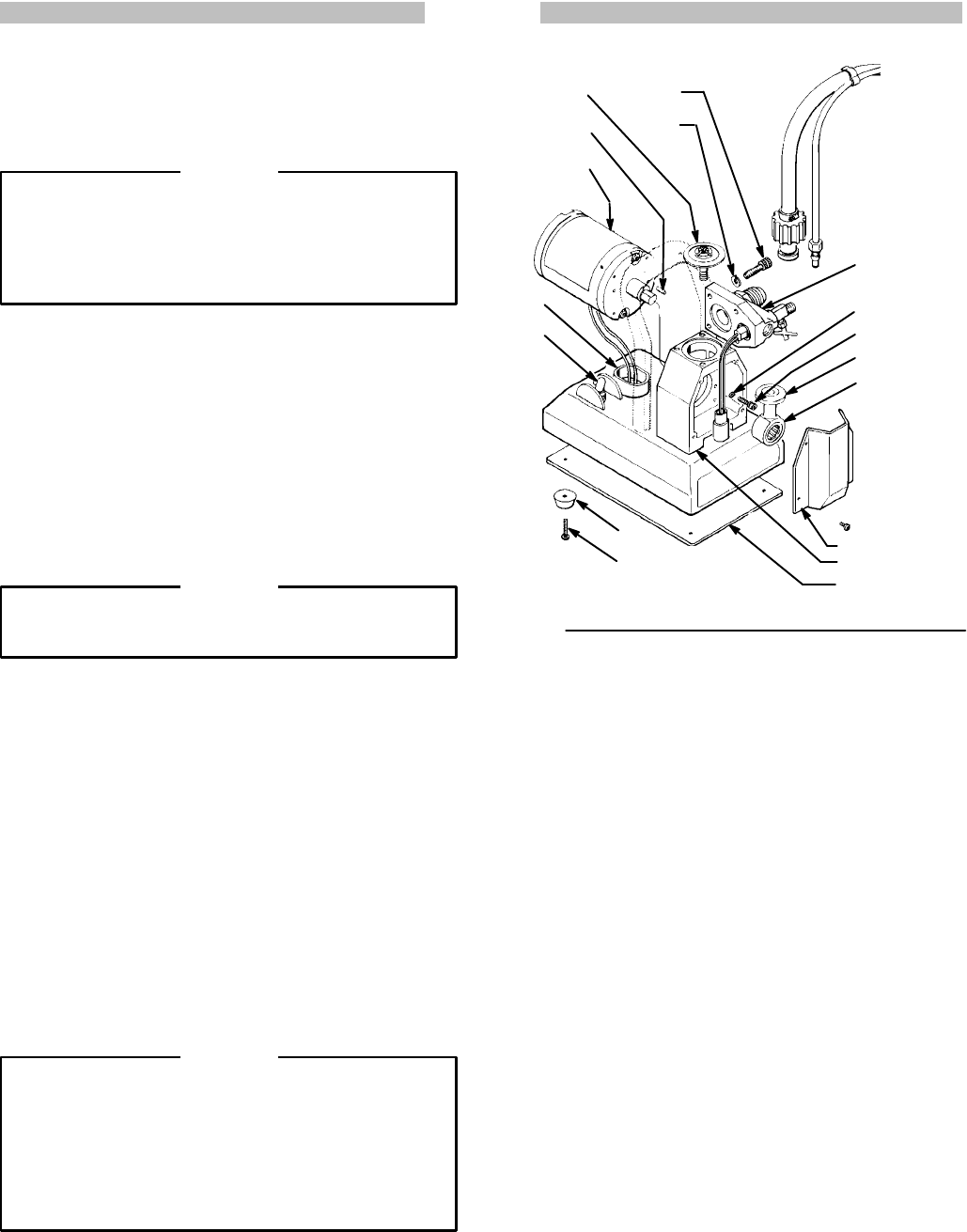
Fig 16
9
21
20
18a
18b
23
22
42
43
33
34
69
17
15
16
PRESS
FIT
INT
O 22
GREASE
BEARING
THOROUGHLY
Motor
(See Fig 16)
1.
Remove the front cover plate (23).
2.
Remove the bumpers (43) and the bottom cover
plate
(42). Disconnect the
motor leads from the posi
-
tive
and negative rectifier terminals. See Fig 1
1, page
12.
3.
Remove
the motor screws. Lift the motor (31)) slight
-
ly. Holding the connecting rod, pull the motor away
from
the housing (22).
4.
Inspect
the bearing (18b)
in the connecting rod (18).
If it is worn or any rollers are broken, replace the
bearing and rod assembly (18) as instructed to the
left.
5.
Use
your fingers to pack high-quality bearing grease
thoroughly
in between the bearing rollers.
6.
Feed the motor leads through the rubber grommet
(69).
Align the motor with the pins in the connecting
rod housing (22), guiding the motor eccentric
through the connecting rod bearing (18b). Spin the
motor
shaft to be sure it moves freely
.
7.
Loosely
install the lockwashers (21)
and screws (20).
Spin the motor shaft again. Alternately tighten the
screws. Spin the motor shaft again. See the CAU-
TION
in Step 8 to the left.
8.
Connect
the red motor lead to the positive (+) termi
-
nal
and the black motor lead to the negative (–) termi
-
nal
of the rectifier (39). Refer to Fig 1
1.
9.
Reinstall the front cover plate.