


3
307–760
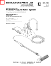
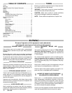
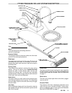
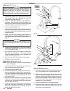
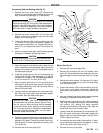
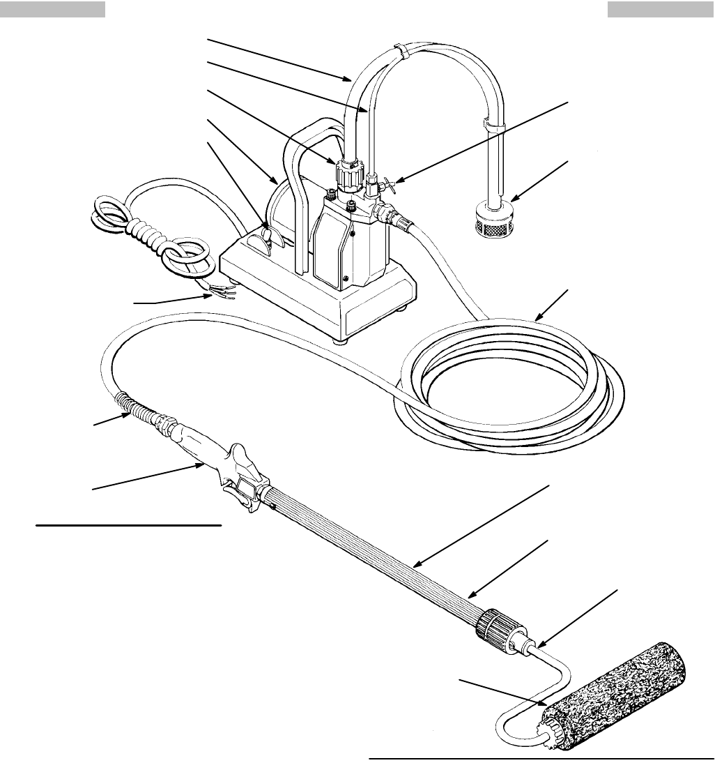
PT2000 PRESSURE ROLLER SYSTEM DESCRIPTION
Motor
The
motor drives the connecting rod which
moves the diaphragm.
Pressure Switch
The pressure switch at the pump outlet turns the motor
on
and of
f to control paint pressure.
Diaphragm
The diaphragm is the heart of the pump. Driven by the
connecting rod and motor, the movement of the dia-
phragm
draws paint from the suction tube and through to
the
outlet valve.
Priming V
alve
The priming valve assists in priming the pump during
startup. Turning the priming valve counterclockwise
causes the paint to drain directly back into the pail
through the priming tube. Turning the knob clockwise
causes
the paint to flow through the fluid outlet valve
and
to
the hose, roller valve and extension.
Outlet V
alve
The outlet valve has a ball check which prevents paint
from flowing backwards into the pump. This helps keep
an
even supply of paint to the roller each time you
trigger
the
roller valve.
Inlet V
alve
As the diaphragm
draws paint from the suction tube the
paint
passes through the inlet
valve which opens to allow
paint
into the pump.
Outlet Hose
The
hose has swivel–type couplings
for easy assembly
.
A
larger diameter outlet hose and chemical-resistant out
-
let
and suction hoses are available. See ACCESSORIES
on
page 17.
Roller V
alve
The
roller valve controls paint flow to the
roller by trigger
-
ing
it on and of
f.
Pressure Roller
The pressure roller has a telescoping extension and a
roller cover for use on smooth surfaces. Longer exten-
sions and different types of roller covers are available.
See
the ACCESSORIES on page 17.
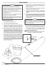
POWER
SUPPL
Y CORD
Add
plug according to
local code
Fig
1
SUCTION
TUBE
PRIMING TUBE
INLET V
ALVE
MOTOR
ON/OFF
SWITCH
PRIMING V
ALVE
P
AINT STRAINER
7.6 M (25 FT) HOSE
460 T
O 920 MM (18 T
O 36 IN.)
TELESCOPING EXTENSION
LOCKNUT
SPRING GUARD
MUST BE A
T
THIS END
ROLLER V
ALVE
ROLLER FRAME
12 MM (1/2 IN.) NAP
ROLLER COVER