


Initial Set Up
311320G 11
Initial Set Up
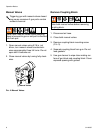
1. Remove coupling block from gun.
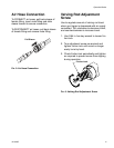
2. Check valving rod clearance in closed posi-
tion. Rod should extend approximately 1/32
in. (1 mm) beyond tip of mixing chamber. If
it does not, see Valving Rod Adjustment
procedure, page 21.
FIG. 9: Valving Rod (Closed Position)
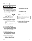
3. Adjust valving rod travel to initial setting.
a. Loosen friction lock. Turn valving rod
adjustment screw clockwise until it
stops.
b. Turn valving rod adjustment screw 11
turns counterclockwise.
4. Connect air supply hose to gun.
5. Connect A-isocyanate hose (red-taped) to
notched fitting on coupling block. Then con-
nect R-resin hose (blue-taped) to fitting
without notches on coupling block.
6. Close both manual valves.
7. Pressurize the A and R chemical hoses
and check for leaks. (See Proportioning
Unit manual.)
8. Bleed air from chemical hoses:
a. Hold coupling block with exit ports
pointed into disposable container.
b. Open each manual valve to allow
trapped air to escape. Bleed each side
until chemical is free of air.
c. Close both manual valves.
9. Use clean cloth soaked in gun cleaner to
wipe clean coupling block and its mating
surfaces.
10.Install coupling block to gun block.
11.Proceed with Daily Start-up procedure or
Shutdown procedure as required.
1/32 in.
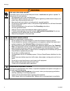
CAUTION
To avoid accumulation of dirt and other con-
taminants, do not apply grease to mating
surfaces of coupling block.