


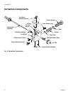
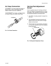
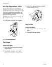
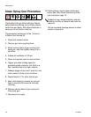
Spray Pattern Adjustment
14 311320G
Spray Pattern Adjustment
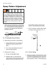
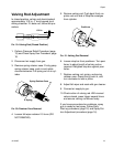
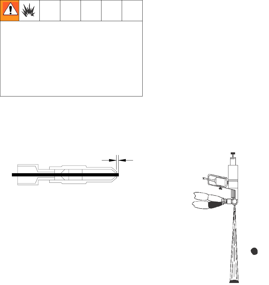
1. Check valving rod clearance in closed posi-
tion. Rod should extend approximately 1/32
in. (1 mm) beyond tip of mixing chamber. If
it does not, see Valving Rod Adjustment
procedure, page 21.
FIG. 10: Valving Rod (Closed Position)
2. Adjust valving rod travel to initial setting.
a. Loosen friction lock. Turn valving rod
adjustment screw clockwise until it
stops.
b. Turn valving rod adjustment screw 11
times counterclockwise.
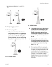
3. Locate point of valving:
a. Aim gun at disposable target.
b. Dispense short (1 second) bursts
toward target while simultaneously with-
drawing valving rod adjustment screw
from retainer case by 1/4-turn incre-
ments in counterclockwise direction.
c. Point of valving is reached when chemi-
cal stream mists as shown in FIG. 11.
FIG. 11: Point of Valving
4. Adjust spray pattern. Note position of notch
in hexhead of adjustment screw, then back
screw out counterclockwise the number of
turns specified in Table 1. Notice spray pat-
This adjustment may create a large mass
“bun” of urethane foam. Very high tempera-
tures created by chemical reaction inside a
bun may not dissipate after outside surface
has cooled. A large bun may continue to react
for several hours after spraying until flash
(burning) point of foam is reached. ALWAYS
break buns into smaller pieces so heat can
escape.
1/32 in.