


-18-
Model G0440/G0441 (Mfg. Since 03/12)
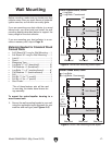
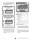
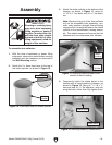
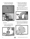
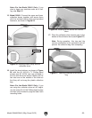
2. Copy the mounting hole layout pattern from
the motor housing (see Figures 7–8) to your
wall mounting board, making sure the Top
Row Mounting Hole Height is correct for
your dust collector.
Use these measurements for hole
placement when mounting the
Model G0441.
Single-Barrel Top Row
Mounting Hole Height = 80"
Double-Barrel Top Row
Mounting Hole Height = 95"
20"
10"10"
G0441 Motor Housing
7
3
⁄4"
80"
or
95
5
⁄8"
Floor
Ø0.55"
Figure 8. G0441 wall mounting layout.
Use these measurements for hole
placement when mounting the
Model G0440.
Top Row Mounting Hole Height = 80"
20
1
⁄2"
10
1
⁄4"
G0440 Motor Housing
7
3
⁄4"
80"
Floor
Ø0.55"
10
1
⁄4"
Figure 7. G0440 wall mounting layout.
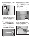
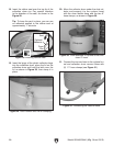
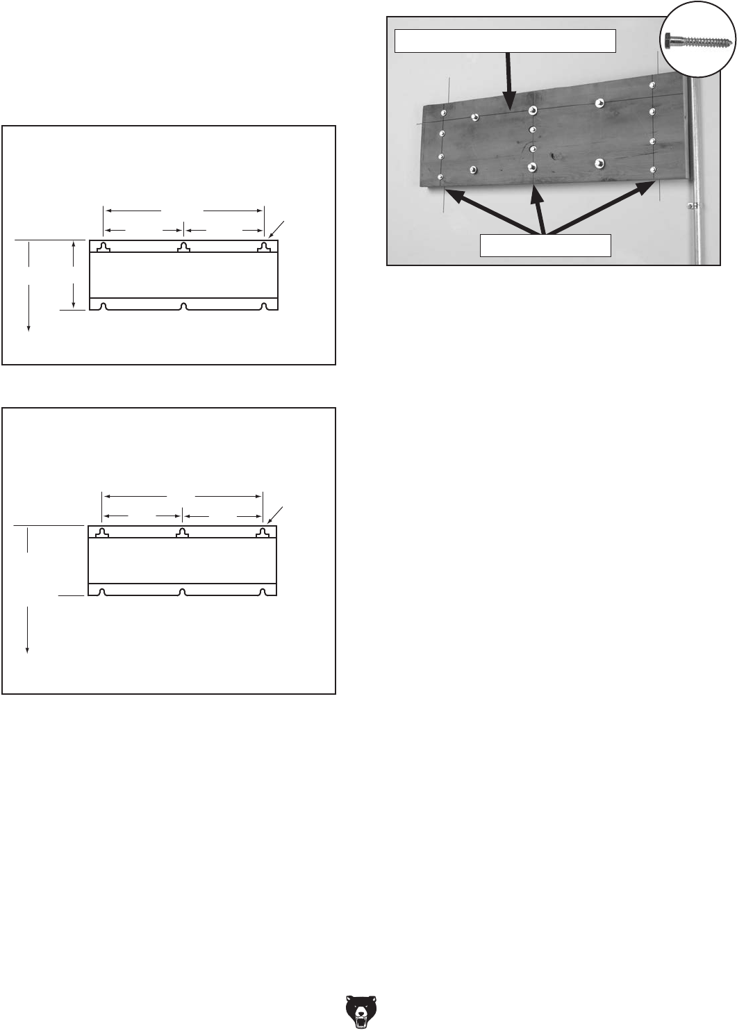
3. Tighten
1
⁄2" lag bolts into the mounting loca-
tions so they do not poke out more than
1
⁄2"
from the mounting board to the top of the
head, but leave them out enough to slide the
housing over. This will prepare you for the
mounting instructions described in Assembly
on Page 19.
Figure 9. Board fastened to wall and ready for
G0440 motor/blower housing assembly.
Top Row Mounting Hole Height
Wall Stud Centers
Materials Needed for Concrete/
Masonry Wall
• Concrete Anchor Stud
1
⁄2" x 2
3
⁄4" ...............8*
• Hex Nuts
1
⁄2" ..............................................8*
• Flat Washers
1
⁄2" ........................................8*
• Hammer Drill .............................................. 1
• Masonry Drill Bit
1
⁄2" ................................... 1
• Level 4' ....................................................... 1
• Pencil .......................................................... 1
• Measuring Tape .......................................... 1
*Two of these fastener sets will be used
in mounting the intake barrel brace during
assembly.
To mount the motor/impeller housing to a
concrete or masonry wall:
1. Copy the mounting hole layout pattern from
the motor housing to your wall, making sure
the Top Row Mounting Hole Height (see
Figures 7–8) is correct for your dust collec-
tor.
2. Mount the anchor studs to the wall in the
mounting hole locations for the motor/impel-
ler housing. This will prepare you for the
mounting instructions described in Assembly
on Page 19.