


Model G0440/G0441 (Mfg. Since 03/12)
-31-
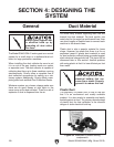
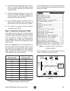
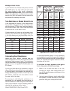
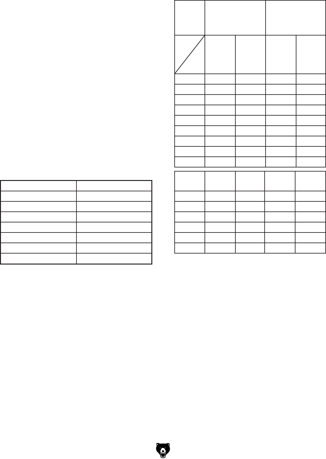
Figure 46. Static pressure loss tables.
Duct
Dia.
Approximate
Static Pressure
Loss Per Foot of
Rigid Pipe
Approximate
Static Pressure
Loss Per Foot
of Flex Pipe
Main
Lines
at 3500
FPM
Branch
Lines
at 4000
FPM
Main
Lines
at 3500
FPM
Branch
Lines
at 4000
FPM
2" 0.091 0.122 0.35 0.453
2.5" 0.08 0.107 0.306 0.397
3" 0.071 0.094 0.271 0.352
4" 0.057 0.075 0.215 0.28
5" 0.046 0.059 0.172 0.225
6" 0.037 0.047 0.136 0.18
7" 0.029 0.036 0.106 0.141
8" 0.023 0.027 0.08 0.108
9" 0.017 0.019 0.057 0.079
Fitting
Dia.
90˚
Elbow
45˚
Elbow
45˚
Wye(Y)
90˚
Wye(Y)
3" 0.47 0.235 0.282 0.188
4" 0.45 0.225 0.375 0.225
5" 0.531 0.266 0.354 0.236
6" 0.564 0.282 0.329 0.235
7" 0.468 0.234 0.324 0.216
8" 0.405 0.203 0.297 0.189
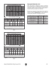
In most small/medium shops it is only necessary
to calculate the line with the longest duct length or
the most fittings (operating under the assumption
that if the line with the highest resistance works,
the others will be fine).
To calculate the static pressure of any given
line in the system, follow these steps:
1.
Make a list of each size duct in the line,
including the length, and multiply those num-
bers by the static pressure value given in
the
previous table.
2.
List each type of elbow or branch and multiply
the quantity (if more than one) by the static
pressure loss given in the previous table.
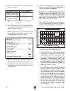
Two Machines on Same Branch Line
Total CFM Branch Line Size
400 4"
500 4"
600 5"
700 5"
800 6"
900 6"
1000 6"
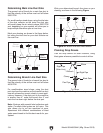
Adding duct work, elbows, branches and any
other components to a duct line increases airflow
resistance (static pressure loss). This resistance
can be minimized by using rigid (smooth) pipe and
gradual curves, as opposed to flexible pipe and
90˚ elbows.
To help you think about this resistance, imagine
riding a bicycle in a tunnel that is an exact replica
of your duct work. If the inside of the tunnel is very
bumpy (flexible pipe) and has a lot of sharp turns
(90˚ elbows), it will take a lot more effort to travel
from one end to the other.
The purpose of calculating the resistance is to
determine if it is low enough from the machine to
the dust collector to meet the given CFM require-
ment for the machine. Use the
following tables
to
calculate the resistance of duct work.
Calculating Duct Resistance
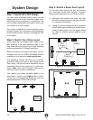
Multiple Dust Ports
If your machine has multiple dust ports, add the
total CFM given for each dust port size from
the table
provided in the earlier subsection,
Determine Required CFMs
, then find the
closest
CFM
in the table below to determine the correct
branch size
. Split the branch line just before the
dust ports with matching duct sizes.
If two machines will connect to the same branch
line and both will operate at the same time, then
add the required CFM for each machine together
and
find the closest total CFM in the table below
to determine the correct branch size
.
If both machines will never run at the same time,
reference the machine with the biggest dust port
in the table below and add blast gates after the
Y-branch to open/close the line to each machine.