-12-
G0508 10 HP Industrial Dust Collector
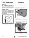
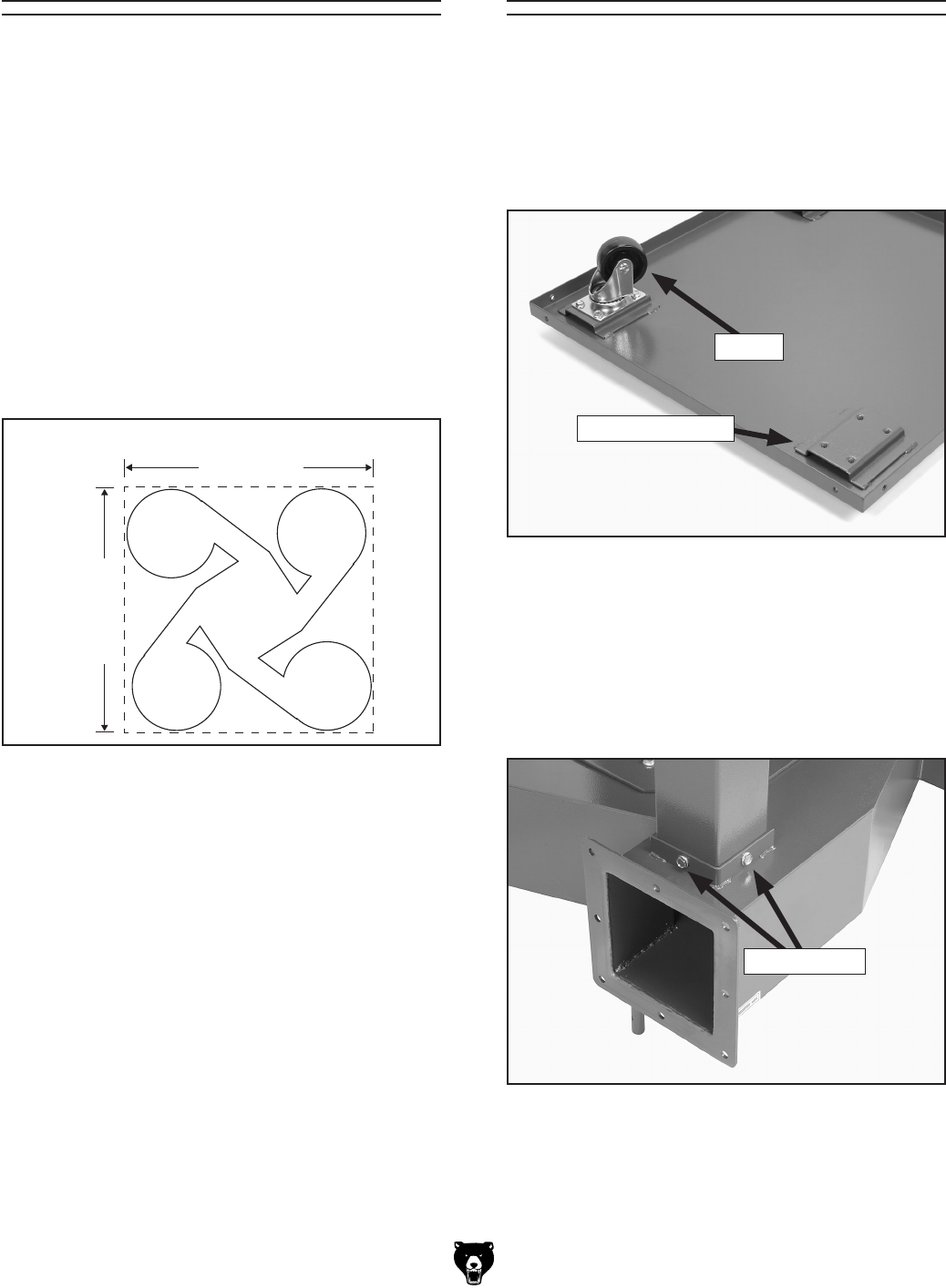
Figure 6. Caster mounted on base.
Caster Mounting
Caster
Floor Load
Refer to the Machine Data Sheet on Page 3 for
the weight and footprint specifications of your
machine. Some floors may require additional
reinforcement to support both the machine and
operator.
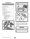
Placement Location
Consider existing and anticipated needs, size of
material to be processed through each machine,
and space for auxiliary stands, work tables or
other machinery when establishing a location for
your new machine. See Figure
5 for the minimum
working clearances.
Site Considerations
Figure 5. Model G0508 illustrated top view and
suggested clearances.
Assembly
To the dust collector system:
1. Place the base upside down on the floor.
2. Attach the casters with the (16)
5
⁄16"-18 x
1
⁄2"
flange bolts (see Figure 6).
3. With assistance, place the main housing on
the floor so that the motor is pointing up.
4. Place the end of the supporting leg with the
threaded holes on the inside of the housing
bracket (see
Figure 7).
Figure 7. Supporting leg mounted to main
housing.
Flange Bolts


