


-4-
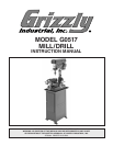
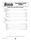
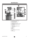
Model G0517 Mill/Drill
The information contained herein is deemed accurate as of 5/12/2006 and represents our most recent product specifications.
Due to our ongoing improvement efforts, this information may not accurately describe items previously purchased.
PAGE 2 OF 3Model G0517
Main Specifications:
Operation Info
Spindle Travel........................................................................................................................................ 3-1/8 in.
Swing................................................................................................................................................... 14-1/2 in.
Longitudinal Table Travel.......................................................................................................................9-1/4 in.
Cross Table Travel.................................................................................................................................5-3/4 in.
Head Swivel.......................................................................................................................................... 360 deg.
Max. Dist Spindle To Column.................................................................................................................7-1/4 in.
Max. Dist Spindle To Table........................................................................................................................ 14 in.
Drilling Cap For Cast Iron..........................................................................................................................5/8 in.
Drilling Cap For Steel................................................................................................................................ 5/8 in.
No. Of Vert. Spindle Speeds...........................................................................................................................12
Range Of Vert. Spindle Speeds.....300, 400, 540, 720, 900, 1040, 1500, 1740, 2100, 2260, 3100, 3840 RPM
Quill Dia..................................................................................................................................................1-7/8 in.
Table Info
Table Length........................................................................................................................................ 16-1/2 in.
Table Width............................................................................................................................................6-1/8 in.
Table Thickness.....................................................................................................................................1-1/8 in.
No. Of T Slots....................................................................................................................................................
2
T Slots Width.............................................................................................................................................1/2 in.
T Slots Height............................................................................................................................................5/8 in.
T Slots Centers......................................................................................................................................
3-3/8 in.
Stud Size...................................................................................................................................................1/2 in.
Lead Screw Info
Lead Screw Diameter............................................................................................................................0.740 in.
Lead Screw TPI.................................................................................................................................................
6
Lead Screw Length.................................................................................................................................... 23 in.
Construction
Spindle Housing Const.........................................................................................................................
Cast Iron
Table Const............................................................................................................. Precision Ground Cast Iron
Head Const...........................................................................................................................................
Cast Iron
Column Const.......................................................................................................................................Cast Iron
Base Const.............................................................................................................. Precision Ground Cast Iron
Stand Const...................................................................................................................................Welded Steel
Paint........................................................................................................................................................Enamel
Other
Collars Calibrated..................................................................................................................................0.001 in.
Column Dia............................................................................................................................................ 2-7/8 in.
Mobile Base..............................................................................................................................................G8683
Spindle Info
Spindle Taper.............................................................................................................................................
MT#3
End Milling Cap......................................................................................................................................... 1/4 in.
Face Milling Cap........................................................................................................................................3/4 in.
Draw Bar Diameter...................................................................................................................................12 mm
Draw Bar TPI..................................................................................................................................... M12 - 1.75
Draw Bar Length.................................................................................................................................. 11-7/8 in.
Spindle Bearings..............................................................................................................................Ball Bearing
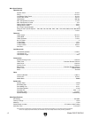
Other Specifications:
ISO Factory ...................................................................................................................................................ISO 9001
Country Of Origin ................................................................................................................................................China
Warranty ............................................................................................................................................................ 1 Year
Serial Number Location ...................................................................................................... ID Label on Head Casting
Assembly Time .......................................................................................................................................... 1-1/2 hours