


-18-
Model G0632 (Mfg. 4/12+)
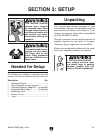
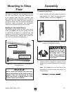
3. Secure the lathe assembly to the supporting
legs with the (8) M10-1.5 x 25 cap screws
and 10mm flat washers (see Figure 12).
Figure 12. Securing lathe assembly to
supporting legs.
4. If you are bolting your lathe to the floor, skip
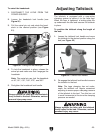
to Step 7. Otherwise, move the tailstock, tool
rest assembly, and headstock to one end of
the lathe bed (see the OPERATIONS sec-
tion beginning on Page 21 for instructions for
moving these components).
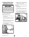
5. Use assistants to lift the light end of the lathe
onto support blocks in preparation for install-
ing the machine feet (see Figure 13).
6. Insert the machine feet into the mounting
holes of the supporting legs, as shown in
Figure 14. Do not tighten the top hex nut yet.
Repeat Steps 5–6 on the other legs.
Figure 14. Machine feet installed.
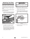
7. Place a level on the lathe bed and make nec-
essary adjustments so that the bed is level
from side-to-side and front-to-back.
—If you are using the machine feet, adjust
the top and bottom hex nuts on each leg to
level the bed; then tighten the hex nuts to
secure these adjustments.
—If you are bolting your lathe to the floor, use
shims under the legs to level the bed; then
tighten the mounting fasteners.
8. Insert the tool rest into the tool rest base and
tighten the tool rest lock lever (see Figure
15).
Figure 13. Example of supporting one end of
lathe in preparation for installing the machine
feet.
Support Blocks
Note: Use assistants to support and stabilize
the lathe while you install the machine feet.
Figure 15. Tool rest installed on the tool rest
base.
Tool Rest Base
Tool Rest
Tool Rest
Lock Lever