


-24-
Model G0632 (Mfg. 4/12+)
2. Re-engage the tool rest base lock handle to
secure the tool rest assembly in position.
Note: The large clamping hex nut underneath
the tool rest base will require occasional
adjusting to ensure proper clamping pressure
of the tool rest assembly to the bed. Turn this
hex nut in small increments to fine tune the
clamping pressure as needed.
To adjust the angle or height of the tool rest:
1. Loosen the tool rest lock handle and adjust
the angle or height of the tool rest.
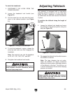
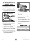
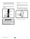
2. Position the tool rest approximately
1
⁄4" away
from the workpiece and approximately
1
⁄8"
above the workpiece center line (see Figure
24).
Adjusting Tool Rest
The tool rest base is equipped with a cam-action
clamping system to secure it to the lathe bed.
When the tool rest base lock handle is tightened,
a locking plate lifts up and secures the tool rest
assembly to the bed. The tool rest can also be
positioned and locked at a specific angle or
height.
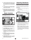
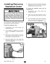
To position the tool rest assembly along the
length of the lathe bed:
1. Loosen the tool rest base lock handle and
move the tool rest assembly to the desired
position on the lathe bed (see Figure 23).
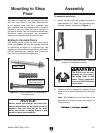
Figure 23. Tool rest controls.
Tool Rest
Lock Handle
Tool Rest Base Lock Handle
Tool Rest
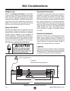
Always operate the lathe with the tool
rest assembly firmly locked in position.
Otherwise, serious personal injury may
occur.
3. Re-tighten the tool rest lock handle to secure
the tool rest in position.
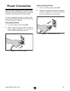
Workpiece
Center Line
Distances
Tool Rest
1
⁄8"
1
⁄4"
Figure 24. Tool rest position relative to
workpiece.