


Model G0756 (Mfg. Since 2/13)
-17-
Power Connection
Before the machine can be connected to the
power source, an electrical circuit must be made
available that meets the minimum specifications
given in Circuit Requirements for 220V on Page
10. If a power circuit has not been prepared for the
machine, do that now.
To minimize the risk of electrocution, fire, or
equipment damage, all installation work and elec-
trical wiring MUST be done by an electrician or
qualified service personnel.
Note about extension cords: Using an incor-
rectly sized extension cord may decrease the life
of electrical components on your machine. Refer
to Extension Cords on Page 11 for more infor-
mation.
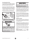
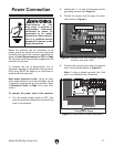
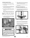
2. Identify the L1, L2, and L3 terminals and the
grounding terminal (see Figure 9).
3. Thread the power cord through the strain
relief shown in Figure 9.
Figure 9. Location of hot wire terminals, ground
terminal, and strain relief.
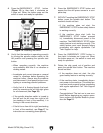
4. Connect the incoming hot wires and ground
wire to the terminals shown in Figure 10.
Note: If using a phase convertor, the "wild
wire" is connected to the L2 terminal.
To connect the power cord to the machine:
1. Turn the master power switch to OFF, then
open the electrical cabinet door located at the
back of the machine.
30 31 32 33 34 35 E
L1 L2 L3 U1 V1
W1 U2 V2 W2 10 12
COM
10 11 12 13 14 15 16 17 QO
PE
Master Power Switch
L
7
5
3
1
8
6
4
2
R
A2
2 T1 6 T3 22NC4 T2
1 L1 5 L3
21NC
Tianshui 123
GSC1-1201
KM1
3 L2
A1
Contactor
A2
2 T1 6 T3 22NC4 T2
1 L1 5 L3
21NC
Tianshui 123
GSC1-1201
KM2
3 L2
A1
Contactor
A2
13NO 23NO 33NO 43NO
14NO 24NO 34NO 44NO
Tianshui 123
JZC3-40d
KA1
A1
Contactor
26 25 24 23 22 21 20
TC
20-21 = 220V
20-22 = 230V
20-23 = 380V
20-24 = 400V
20-25 = 415V
20-26 = 440V
Transformer
To Plug/Power Supply
To High/Low
Gear Switch
To Electronic
Clutch
To Control
Panel
To
Pump
JBK5-100VATH
ON
OFF
ON
OFF
ON
OFF
ON
OFF
ON
OFF
CM X11 X13 CM X15 X17 CM
• • X10 X12 • X14 T +24v
Special Controller
EX-30tA1-B
E&E
••••••••
CM
2
CM
2
•••••Y7Y6Y5Y4
U2 V2 W2
QM5 QM3 QM2 QM1 QM4
CM
0
36
35
35
36
Q3
U1
U1
V1
V1
W1
W1
2L3
2L3
ZL22L13L1 3L3
2L1
3L13L3
22
21L3L2L1
1131
20 X1X3
CM
22
Q2
Q3
Q0
Y0
Q1
Y3Y2Y1
CM
2
CM
1
12
12
10
X2
X4X6
3021 11103120
X5X7
L X1 X3 CM X5 X7
N X0 X2 X4 X6
30
12
2L1 ZL2 2L3
2L3ZL2
ZL2
2L1
3L1
3L3
1010
Q1
10
32
32
L1
L3
L2
CanSen
LW26GS-20
C1 C3 D1 D10 C1
DZ451-63 DZ451-63 DZ451-63 DZ451-63 DZ451-63
KBPC10-10
L1 L2 L3 U1 V1
W1 10 12 X1U2 V2 W2 X2 X3 X4 X5 X6 X7 QO
COM
PE
L1 L2 L3 U1 V1 W1 U2 V2 W2 10 12 X1 X2 X3 X4 X5 X6 X7 QO
L1
L2
L3
COM
COM
Mager
PLC
Q2
PE
Figure 10. Ground and hot wires connected.
Grounding Terminal
Strain Relief
L3L1 L2
Electrocution or fire
may occur if machine is
ungrounded, incorrectly
connected to power, or
connected to an under-
sized circuit. Use an electri-
cian or a qualified service
personnel to ensure a safe
power connection.