


G1067Z Wood Lathe -9-
Installing the Switch
Figure 5.
Figure 6.
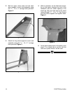
1. Locate the on/off switch and the front and
rear covers which will be held in place by two
Phillips
®
head screws.
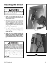
2. Make sure the wiring from the switch goes
through the rear cover box. Position the
switch in the opening in the left front leg of
the stand. Figure 5. Attach the two green
ground wires to the stand (see arrow) using
the Phillips
®
screw provided.
3. Line up the front cover, the switch and the
rear cover with the holes in the stand and
attach using two 10 - 24 x 1" Phillips
®
head
screws and nuts.
4. Locate the plug-in connector coming from
the motor and connect it with the connector
coming from the switch. Figure 6 shows a
properly assembled switch and the connec-
tor.
Do not plug cord in until you are ready to
test run the lathe. See Test Run section for
instructions before initial run.
This equipment must be grounded. Please
ensure that this machine is continuously
grounded from the motor to the machine
frame and then to a known ground. Verify that
any existing electrical outlet and circuit you
intend to plug into is actually grounded. If it is
not, it will be necessary to run a separate 12
A.W.G. copper grounding wire from the outlet
to a known ground. Under no circumstances
should the grounding pin from any three-
pronged plug be removed. Serious injury
may occur.