G1148 15" Bandsaw -13-
DO NOT attempt to operate this machine
before completing the assembly and adjust-
ment instructions. Be sure that the switch is
off and the cord is disconnected from the
power source at all times until assembly
and adjustment are complete and you have
reviewed all safety guidelines. Serious
injury could occur.
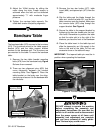
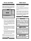
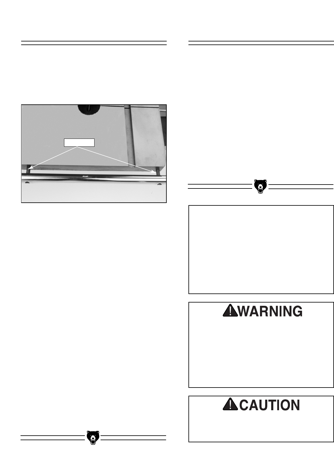
Figure 7. Rail attachment points.
Fence and Rails
The saw blade is dangerously sharp. Use
extra care when handling the blade, or work-
ing near it. Serious injury is possible.
Table Insert
The table insert provides support for materials
being cut. It can also be removed for increased
access to the lower blade guide.
The insert is supported by a lip formed in the
table casting. No adjustment should be neces-
sary beyond placing the insert in the hole in the
table top.
The insert should be flush with the table top when
inserted in position. If the insert sits too high in
relation to the table, inspect the bottom of the
insert and the top of the lip. If burrs or bumps
exist, use a fine flat file or a rotary tool to smooth.
If the insert fits too low, use small pieces of mask-
ing tape to raise the level of the insert.
The last item to install is the rip fence (assembled
around #114). Notice that the front and back
edges of the table have four (4) counterbored and
threaded holes. These holes accept the spacers
(#86) and cap screws (#88) that attach the fence
rails to the table (#87). See Figure 7.
1. Secure the fence rails to the table with the
four (4)
1
/4" - 20 x
3
/4" cap screws and spac-
ers provided. For maximum fence travel to
the left of the blade, install the rails so the
longer 10
3
/4" segment between the end of
each rail and the mounting hole is located
to the left side of the table (facing the front
of the bandsaw).
2. To mount the fence on the left side of the
blade, remove the blade from the bandsaw.
If you wish to mount the fence to the right
side of the blade, it will be necessary to
remove the fence from the rails before
changing blades.
3. The fence locking handle and knob should
both be loose (#107, #91). Slide the fence
onto the fence rails. Ensure that the fence
slides easily. Give the fence rails a shot of
light oil or silicon spray if needed.
NOTE: When the fence is to the left of the blade,
the fence must be positioned near the center of
the table in order to open the lower wheel cover.
Rail Spacers
NOTICE
Though the notch in the insert has been
engineered to remain unobstructed at all
table angles, use care to inspect blade
clearance when preparing to make angled
cuts. If the blade touches the side of the
insert, refer to the blade guide, and blade
tensioning and tracking adjustments in the
next section.


