


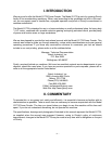
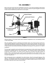
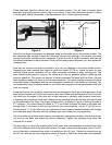
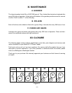

Three setscrews hold the column cap to the horizontal column. You will need to loosen those
setscrews to properly seat the column cap on the column. Two of the setscrews are seen in Figure
3. At this point, attach the handles to the handwheels with a 12mm open end wrench.
- 7 -
2.75"
2.75"
3/8" (Through Bolt)
"F" Bit (Tapped)
Figure 3
Figure 4
Once the first three components are attached, snug up the guide bolt on the column bracket. The
bolt should be tight enough to keep the horizontal column from twisting in the bracket, yet loose
enough to allow for smooth column movement. Tighten the bolt in small increments and turn the
horizontal handwheel to test movement. Once you’ve found proper adjustment, you can tighten the
clamping lever.
Now that the columns are properly attached, let’s turn our attention to the power feeder’s base.
Depending on what machine you intend to install the Model G1778 on, locate the point on your
machine’s table where installation will not affect movement of fences or other moving parts. The
base should be mounted as close to the actual work area as possible, without interfering with
machine operation. The shorter the amount of distance between the base and the rollers, the less
likely the power feeder will torque out of its desired position. You might consider mounting the base
on a stable piece of hardwood with the mounting bolts countersunk in the bottom of the wood. You
can temporarily mount the power feeder on your table with clamps to find the base location that best
suits your needs.
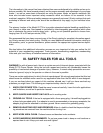
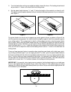
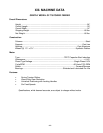
Using the base as your template, locate the best mounting point. Mark the outside perimeter of the
base and the locations of the four bolt holes on your table. Measure the distances of the four mount-
ing holes from the edges of the table with a tape measure or yardstick and compare those mea-
surements with the bottom of the table. Make sure the mounting holes will not align with cast braces
on the underside of the table. The proper drilling pattern, as shown in Figure 4, features 4 holes at
2
3
/4" distance. The holes should be drilled at
3
/8" if you intend to attach the base to the table with
through bolts. If you intend to drill and tap holes for your mounting bolts, use an “F” drill bit in con-
junction with a
5
/16-18 tap. When you are satisfied you have properly located the base, drill through
your table and attach the base with the fasteners you have chosen for your application.
Once the holes are drilled and the base is mounted with appropriate hardware, loosen the clamp-
ing lever on the base and attach the column assembly. Tighten the clamping lever when the
columns are in place.
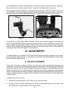
The next step is to attach the angular joints to the motor and roller assembly and attach that entire
unit to the outboard end of the horizontal column. To begin, connect the two angular joints. The 45°
joint is fitted with a threaded knob which is inserted into the 90° joint. Tighten the locking lever on
the 90° joint with the two joints aligned as shown in Figure 5. Attach the motor and roller assembly