- 9 -
3. Turn the feed rollers so they are angled just slightly toward the fence. The leading wheel should
be just about
1
/4" closer to the fence than the trailing wheel.
4. Set the wheel height between
1
/16" and
1
/8" below the height of the material you intend to mill.
The wheels, when properly adjusted, will put consistent downward pressure on your workpiece.
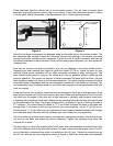
See Figure 7.
Figure 7
Figure 8
The power feeder can also be set to support your work against a fence, as shown in Figure 8. As
with the previous arrangement, the rollers should be slightly angled to hold the workpiece against
your cutting surface. This arrangement is ideal for milling edges and when using the power feeder
with a jointer. When using the power feeder this way, it is essential to make sure that the fence is
fastened tightly in place. As before, you will want to set the distance between the rollers and (in this
case) the fence about
1
/16
" to
1
/8
" under the thickness of the material to be milled. When used on its
side, you will want to adjust the rollers so the leading wheel is about
1
/4" closer to the table than the
trailing wheel.
There are three important factors to consider when using the power feeder with a table saw; pinch-
ing, binding and blade height. If you are ripping boards 4" or wider, place the power feeder between
the fence and blade with the rollers turned slightly toward the fence. If you are ripping materials less
than 4", set the rollers as close as possible to the fence. It is important, in this case, that you don’t
set the rollers so the waste side of your material binds or pinches the blade. The rollers should be
angled with no more than
1
/8" of variation between the leading and trailing wheels.
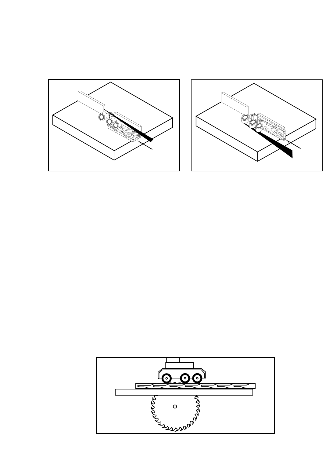
IMPORTANT: It is essential, when ripping narrow materials, that the blade height on your table saw
be at, or just slightly below the bottom of your rollers. See Figure 9. If the material you are cutting
requires you to place the saw blade directly below you rollers, set your saw blade slightly below the
full thickness of your workpiece.
Figure 9


