


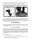

to the angled joints. The roller casing mounts in an identical fashion as described for the angle joints.
Attach the knob on the roller casing to the 45° angle joint and tighten the locking lever.
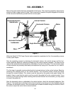
Once the motor and roller assembly is attached to the angle joints, attach the entire unit to the col-
umn assembly. The column clamp may need to be spread slightly to attach it to the horizontal col-
umn. Use extreme care when spreading the clamp. Too much force could break the casting.
- 8 -
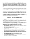
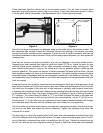
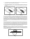
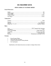
Figure 5
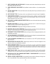
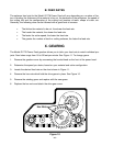
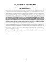
Figure 6
It’s essential, for proper power feeder operation, that the feed rollers be parallel to the machine’s
table. To adjust the power feeder, lower the horizontal column using the handwheel at the top of the
vertical column, until the rollers contact the table. If the rollers touch unevenly, loosen the locking
lever on the 45° angular joint and continue to lower the horizontal column until all of the rollers are
touching the table evenly. Re-tighten the locking lever.
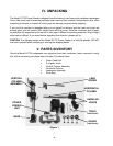
IX. ADJUSTMENTS
The effectiveness of your Model G1778 Power Feeder depends on proper placement of the rollers
and the speed at which they turn. In this section, we will look at the the adjustments that will opti-
mize power feeder performance.
A. ROLLER PLACEMENT
If you look at the rollers, as shown in Figure 6, you will notice that the gap between the leading and
middle roller is larger than that between the middle and trailing roller. That arrangement allows you
to place the rollers so the first wheel is slightly ahead of your cutting tool, while the middle and third
wheels are behind. Thus, the rollers feed your workpiece into, through and past the cutting surface
without contact between the wheels and cutter. Positioning the roller assembly this way not only pro-
vides a consistent application of power to the workpiece, it also acts to keep your hands away from
cutting surfaces.
To position the rollers correctly:
1. Raise the horizontal column so the rollers are just above the table.
2. Swing the motor and roller assembly so the rollers are just slightly away from the cutter, with
the leading roller slightly forward of the cutting surface.
Trailing
Wheel
Leading
Wheel