


G3105 Combination Sander -9-
SECTION 4: ASSEMBLY
Overview
All die-cut metal parts have a sharp edge
(called “flashing”) on them after they are
formed. This is generally removed at the
factory. Sometimes a bit of flashing might
escape inspection, and the sharp edge may
cause cuts or lacerations when handled.
Please examine the edges of all die-cut
metal parts and file or sand the edge to
remove the flashing before handling.
Most of your G3105 Belt and Disc Sander has
been assembled at the factory. The few pieces
that remain should go together quickly and easi-
ly. Only a few common tools are required to
assemble your Combination Sander. Specifically,
these are: 12mm open end wrench, Phillips
®
head screwdriver, 8mm Allen
®
wrench (provided
with machine). The following list provides the rec-
ommended order in which the sander should be
assembled:
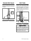
• Outside Belt Guard
• Belt Table
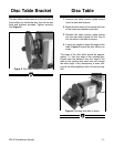
• Disc Table Bracket
• Disc Table
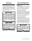
Before beginning the assembly process, we rec-
ommend you become familiar with the Model
G3105 Combination Sander’s parts and controls.
See Figure 2 below, as well as the Parts Diagram
at the end of the manual for details.
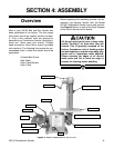
Figure 2. Major components of the G3105.
TENSION KNOB
MITER GAUGE
BELT TABLE
GUARD MOUNTING KNOB
TRACKING SCREW
SWITCH
TABLE TRUNNION
ANGLE GUIDE SCREW
SANDING DISC
DISC TABLE
HORIZONTAL ADJUSTMENT SCREW
BELT TABLE ADJUSTMENT SCREW
MOTOR BODY