


-18- G4186Z 18" Bandsaw
Guide Blocks - The guide blocks ensure that
the blade is not pushed too far laterally. To
adjust the guide blocks, loosen the thumb-
screws that secure the guide block shafts.
Adjust them evenly so that the front of the
blocks are
1
/64" behind the gullet line of the
blade. Tighten these thumbscrews. Now
loosen the guide block thumbscrews. The
ideal distance between the blade and each
guide block is .004". This measurement is
approximately the same as the thickness of a
piece of paper or a dollar bill. For a quick
gauge, fold a dollar bill in half, slide it over the
blade so each half covers each side of the
blade. Set the blade guides so each one
touches the dollar bill. Be careful not to move
the blade in either direction while you are per-
forming this adjustment. Tighten the blade
guides. The result of this adjustment should
leave a .004" distance between the blade and
each of the blade guides.
LOWER GUIDES
Adjustments for the lower guides are identical to
those for the upper guides, except that the bear-
ing and guide block positioning is controlled by
setscrews. Use Figure 17 to identify the lower
guide assembly components.
Blade Guides
Whenever changing a blade or adjusting tension
and tracking, the upper and lower blade support
bearings and guide blocks must be re-adjusted.
Always adjust the assemblies away from the
blade before installing a new blade or making
blade tracking adjustments. After blade tension
and tracking are set correctly, re-adjust the upper
and lower support bearings and the guide block
assemblies into position. See Figures 16 and 17
for locations.
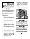
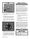
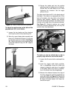
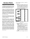
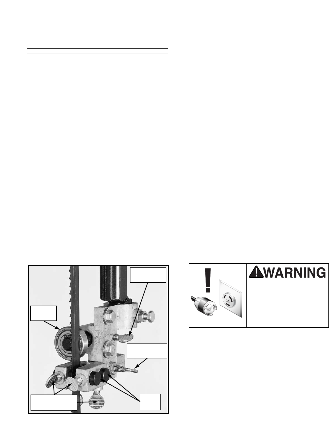
Guide
Blocks
Support
Bearing
Guide Bracket
Thumbscrew
Bearing
Thumbscrew
Guide Block
Thumbscrews
Figure 16. Upper guide adjustments.
UPPER GUIDES
Adjustment of the upper guides is a two-part pro-
cedure, consisting of adjustments to both the
support bearings and the guide blocks.
Support Bearings - The support bearing runs
against the back edge of the blade to keep it
from being pushed out of position by the
advancing workpiece. To adjust the support
bearing, loosen the thumbscrews securing the
support bearing shaft. Push or pull the shaft so
that the upper support bearing is within
1
/64" of
the back edge of the blade. Retighten the
thumbscrews.
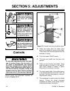
Disconnect power to the
machine when perform-
ing any adjustments or
maintenance. Failure to
do this may result in seri-
ous personal injury.