


<.'). &'m(,7Zai9g^kZ<Ve7ZYAVi]Z
"(,"
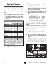
Setting Feed Rate
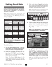
;ZZYgViZ^hYZiZgb^cZYWni]ZbVX]^cZYbViZg^Va!
i]ZineZd[idda^c\jhZY!VcYWni]ZYZh^gZY[^c^h]#
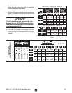
GZ[Zg i]ZiVWaZ ^cFigure 52 dg i]ZMachinery's
Handbook[dg\j^YZa^cZh#
Note: These instructions are valid only for feed
rod power feed. Feed rate configuration for thread-
ing is discussed in the Threading subsection
starting on Page 40.
Recommended Feed Rates
Ldg`BViZg^Va
BV\cZh^jb
6ajb^cjb
7gVhh7gdcoZ
8deeZg
8Vhi>gdcHd[i
8Vhi>gdc=VgY
B^aYHiZZa
8VhiHiZZa
IddaHiZZa
6aadnHiZZah=VgY
HiV^caZhhHiZZa
I^iVc^jb
=^BV\VcZhZHiZZa
Idda;ZZYGViZ>EG
Rough Cuts Finish Cuts
%#%&*¶%#%'*
%#%&*¶%#%'*
%#%&*¶%#%'*
%#%&%¶%#%'%
%#%&*¶%#%'*
%#%&%¶%#%'%
%#%&%¶%#%'%
%#%&%¶%#%'%
%#%&%¶%#%'%
%#%&%¶%#%'%
%#%&%¶%#%'%
%#%&%¶%#%'%
%#%&%¶%#%'%
%#%%*¶%#%&%
%#%%*¶%#%&%
%#%%(¶%#%&%
%#%%)¶%#%%-
%#%%*¶%#%&%
%#%%(¶%#%&%
%#%%(¶%#%&%
%#%%(¶%#%&%
%#%%(¶%#%&%
%#%%(¶%#%&%
%#%%(¶%#%&%
%#%%(¶%#%&%
%#%%(¶%#%&%
Note: These values are a guideline only. Refer
to the MACHINERY’S HANDBOOK for more
detailed information.
Figure 52.;ZZYgViZiVWaZ#
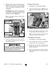
To set the feed rate:
1. JhZ i]Z he^cYaZ Y^gZXi^dc aZkZg id ijgc i]Z
he^cYaZOFF!i]ZcVaadli]Zhe^cYaZidXdb"
eaZiZanhideWZ[dgZbV`^c\\ZVgX]Vc\Zh#
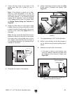
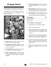
2. BV`ZhjgZi]ZX]Vc\Z\ZVghVgZ^ci]ZXdc"
[^\jgVi^dc )%I$&',I$)%I! Vh ^aajhigViZY ^c
Figure 53gZ[ZgidChange Gears dcPage
38[dgYZiV^aZY^chigjXi^dch#
Note: The Model G9249 ships with the
change gears in the 40T/127T/40T configu-
ration, which will cover most feed rates and
inch threading.
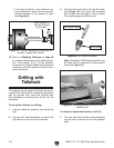
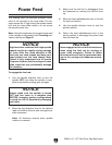
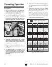
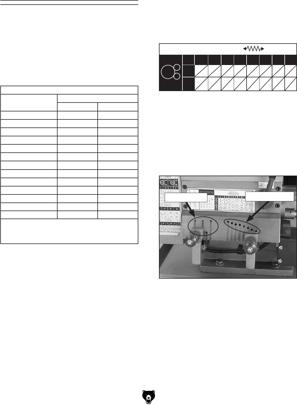
Figure 54.;ZZYgViZhZaZXidgh#
AZiiZg>cYZcih
CjbWZg>cYZcih
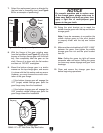
3. GZ[Zgidi]ZiVWaZ^cFigure 53 VcY[^cYi]Z
kVajZXadhZhiidndjgYZh^gZY[ZZYgViZZ^i]Zg
^cb^aa^bZiZgheZggZkdaji^dcidekVajZhdg^c
^cX]ZheZggZkdaji^dcWdiidbkVajZh#
Note: This table is also on the bottom of the
label to the left of the feed rate selectors.
4. Ejaa i]Z `cdW d[ i]Z [ZZY gViZ hZaZXidg VcY
gdiViZ^iYdlc#A^cZjei]ZhZaZXidgl^i]i]Z
YZh^gZY ^cYZci! gdiViZ i]Z hZaZXidg je! VcY
Vaadli]Ze^cidZc\V\Z^cidi]Z^cYZcihZZ
Figure 54#
Note: It may be necessary to jog the spindle
to facilitate movement of the selectors.
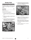
FEEDING TABLE
mm
/inch
127
40
40
D
E
12345678
.42 .37 .35 .33 .30 .28 .26 .24
.0165 .0146 .0138 .0131 .0120 .0110 .0101 .0094
.210 .185 .175 .165 .150 .140 .130 .120
.0082 .0073 .0069 .0065 .0060 .0055 .0050 .0047
Figure 53.;ZZYgViZiVWaZ#
For Example: The operation is a shallow
finish cut on an aluminum workpiece. The
chart in Figure 52 recommends a feed rate
of 0.005–0.100 IPR (inches per revolution).
Because this is a shallow cut, we could select
a feed rate of 0.0082 IPR. To set this feed
rate, seat the left feed rate selector in the
"E" indent, and the right selector in the "1"
indent.