


-24- Extreme Duty Planers
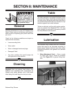
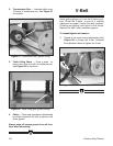
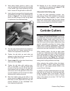
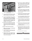
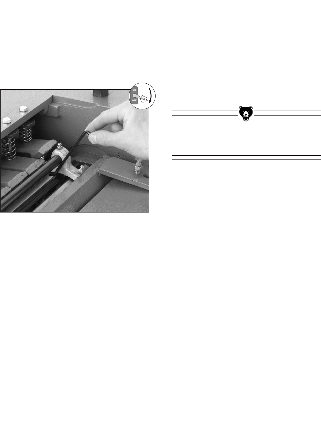
Figure 9. Adjusting knife jack screws.
5. Turn the jack screws with the hex wrench to
raise the knife so it barely touches the jig.
Perform this adjustment on both ends.
6. Tighten the gib bolts on each side just
enough to keep the knife from moving—DO
NOT fully tighten at this time.
7. Repeat steps 2-6 on the other three knives,
then move on to step 8
.
8. Tighten the gib bolts, with medium pres-
sure, in this order: (1) The two center bolts
on each of the four knives, (2) the next two
bolts outward from the center of each knife,
and (3) the rest of the gib bolts in this man
-
ner until all bolts on all four knives have been
tightened with medium pressure.
9. Now final tighten each of the bolts in the
same manner as step 8. Tightening the gib
bolts two at a time, each knife at a time, will
prevent distortion of the cutterhead from
over-torquing the gib bolts.
3. Wear heavy leather gloves or place a rag
over the exposed knife to protect your hands
if the wrench slips while loosening the gib
bolts. Loosen all the gib bolts on one knife.
4. Insert a 4mm hex wrench into the jack screws
(accessible from holes in the cutterhead) as
shown in Figure 9. Turn these screws to
lower the knife enough to clear the jig when
it is placed on the cutterhead body.
10. Replace all of the removed planer parts
and adjust the pressure bar (pages 17-18
)
before operating the planer.
Aftermarket Knife Setting Jigs
To ease the knife adjustment process, con
-
sider using a Planer Pal
®
available in the current
Grizzly catalog. Using magnets, a pair of these
devices will automatically hold the knife blades
within .001" of each other, thereby allowing you to
quickly and accurately lock the knife in place.
Carbide Cutters
The Models G9740Z/G9967Z/G9961 feature spi-
ral cutterheads. These spiral cutterheads cut with
indexable carbide inserts which have four cut
-
ting edges. Although only one edge can cut at a
time, the inserts can be easily rotated when they
get dull, essentially providing four factory sharp
edges before requiring replacement. Indexable
inserts never need to be adjusted for height, only
rotated and securely fastened to the cutterhead.
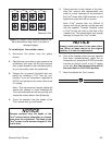
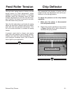
When rotating cutters, the dot on each cutter
is used as a reference point when determining
which cutter edges are used, or dull, and which
are sharp. Be sure to always rotate the cutters in
the same direction (see Figure 10
). Otherwise,
the dot will not be an effective reference for deter
-
mining which cutting surfaces are sharp.
When replacing the carbide cutters, the dimen
-
sions are 14mm x 14mm x 2mm, with a 6.5mm
bore and 30° relief angles (Model H2334 in the
current Grizzly Catalog).
In addition, the spiral cutterhead planers are sup
-
plied with an air wrench for loosening and tight
-
ening the carbide cutter Torx
®
screws. This tool
is very valuable if you have to rotate or change
many of the cutters at one time. T-20 Torx
®
bits
are also included.