


Extreme Duty Planers -27-
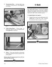
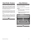
To check the table with the block of wood:
1. Make sure the planer is disconnected
from the power source!
2. Models G9740Z and G9967Z skip this step.
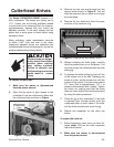
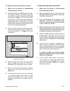
For Models G9740 and G9967, open the
left side service door. Locate the cutterhead
lock shown in Figure 11. Pull up and twist
so the end of the lock will drop. Rotate the
pulley to line up the cutterhead lock with the
THREADED HOLE in the pulley (this should
position the cutterhead so the knives are out
of the way for table adjustments).
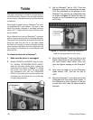
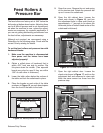
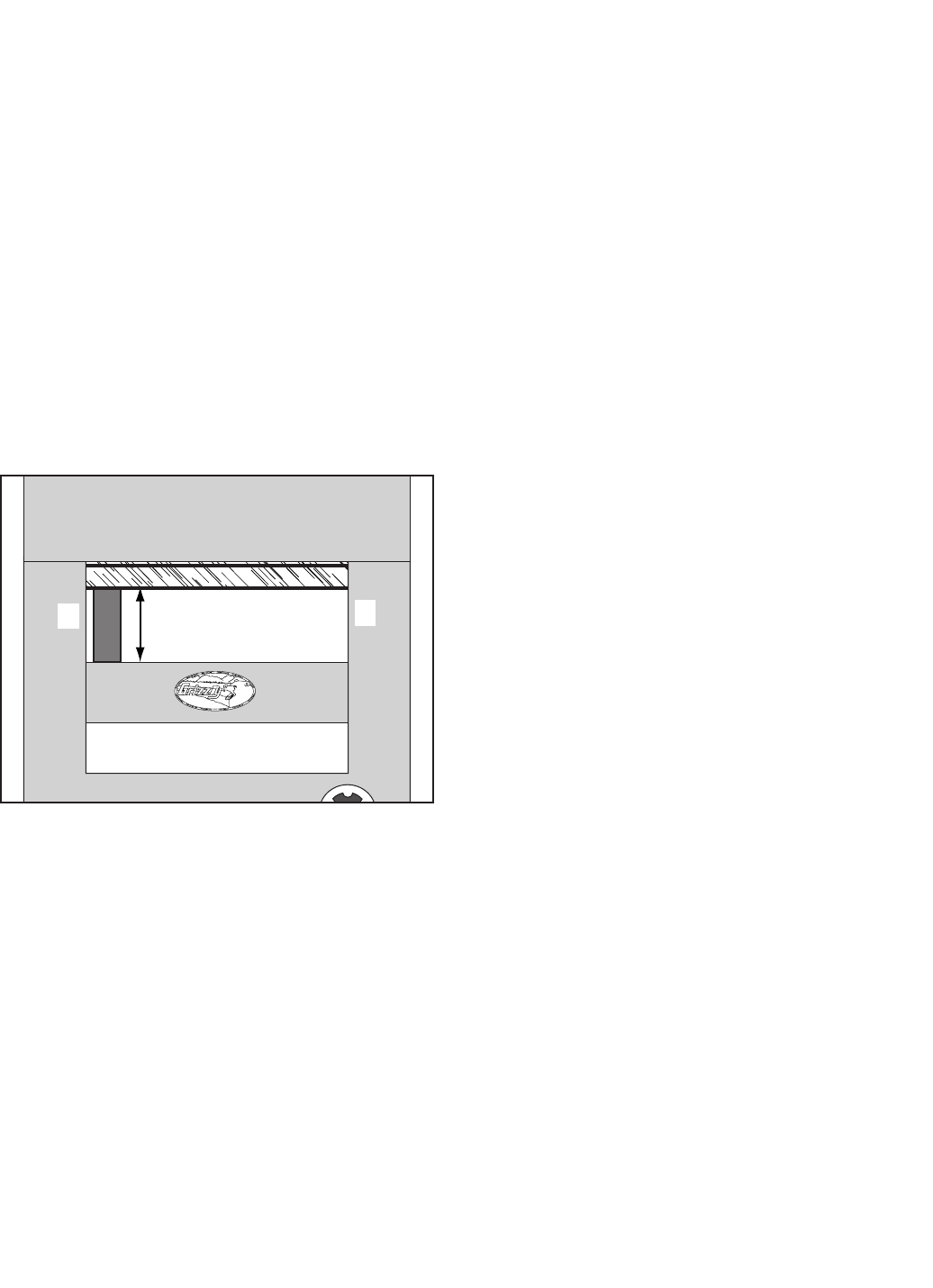
3. Place the block of wood on the table, under-
neath the cutterhead. Position the block on
the left side (point “A” in Figure 13) of the
cutterhead.
Figure 13. Measure table-to-cutterhead at both
points “A” and “B.”
A
B
CUTTERHEAD
TABLE
*
A
B
To adjust the table with the Rotacator
®
:
1. Make sure the planer is disconnected
from the power source!
2. Set the Rotacator
®
dial to .000". Place the
Rotacator
®
under the cutterhead on the right-
hand side (facing front).
3. Turn the cutterhead so the plunger on the
Rotacator
®
contacts the cutterhead body.
Raise the table up enough for the cutterhead
to get a reading on the dial.
4. Move the Rotacator
®
back and forth to find
bottom dead center on the cutterhead. (You
will reach bottom dead center when you have
the highest reading on the Rotacator
®
.)
5. Adjust the table height to make the dial on
the Rotacator
®
read .050", then set the dial
to .000". Move the Rotacator
®
over to the far
left end of the cutterhead and find bottom
dead center.
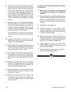
6. Locate the two columns underneath the
table. These are covered in flexible rubber
sleeves. Underneath the sleeves are adjust
-
ment flanges that allow you to disengage the
table columns from the lifting gears.
To adjust the table, you need to disen-
gage the opposite side from that which
needs to be adjusted.
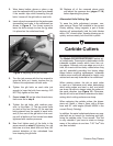
7. Pull the rubber sleeve down on the deter-
mined column to expose the table adjust
-
ment flange shown in Figure 14. You may
need to cut the plastic cable tie in order to
remove the sleeve.
4. Raise the table up until the top of the block
lightly contacts the bottom of the knife or
indexable insert, depending on your model.
5. Without moving the table position, slide the
block over to the other side (point “B” in
Figure 13
).
6. If the block will not fit under the cutterhead
or if the gap between the block and the
cutterhead exceeds .004" (use a feeler
gauge to measure this), the table must be
adjusted.