


Extreme Duty Planers -25-
NOTICE
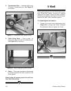
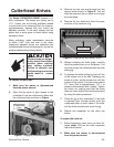
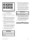
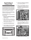
Always rotate each insert in the same direc-
tion. When an insert returns to the original
position, it is time for replacement.
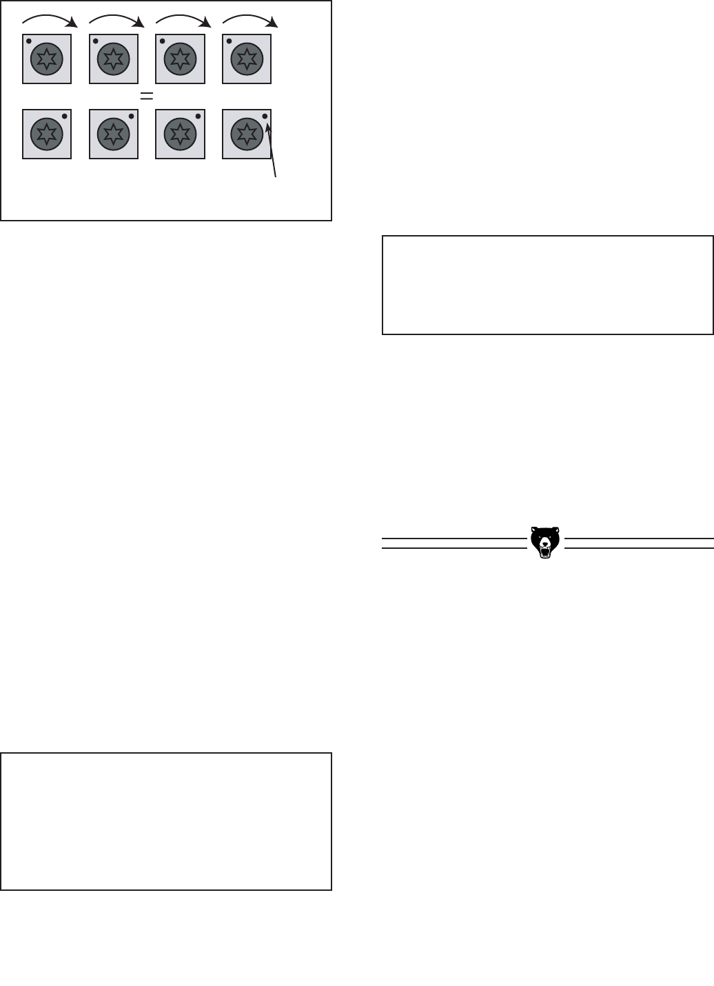
Figure 10. Always rotate carbide cutters in the
same direction to keep track of the dull or
damaged edges.
Reference Dot
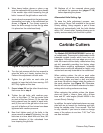
NOTICE
Remove sawdust from the heads of the
Torx
®
screws before attempting to remove
them from the cutterhead. The head of the
Torx
®
screws could become stripped if this
is not done.
To install/adjust the carbide cutters:
1. Disconnect the planer from the power
source!
2. Open the top cover door to gain access to the
cutterhead, and open the left-hand service
door to gain access to the cutterhead pulley,
so you can safely rotate the cutterhead.
3. Prepare the air wrench (included with your
planer) by installing a T-20 Torx
®
bit, con-
necting it to an air compressor regulated to
30 PSI, and setting the air wrench dial to the
“2” setting.
Note—This low pressure (torque) setting will
reduce the chance of cross threading the
Torx
®
screw threads as well as correctly pre-
torque the screws before final tightening.
4. Clean out sawdust from the heads of the
Torx
®
screws that you will loosen.
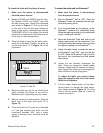
5. Paying attention to the location of the refer-
ence dot, remove and replace/rotate one
cutter at a time, sparingly oil the threads of
the Torx
®
screw with a light machine oil, and
tighten the screw with the air wrench.
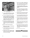
Note—Torx
®
screws that are difficult to
remove with the air wrench can be removed
with the supplied T-handle. Carefully insert
a Torx
®
bit into the hole on the side of the
“cheater bar.” This should allow you enough
leverage to loosen the Torx
®
screws.
6. After all the carbide cutters that you adjusted
have been rotated/replaced, adjust the air
compressor air pressure to 82 PSI and make
sure the air wrench is still at the “2” setting
on the dial (this final torque setting will be
the equivalent of 48-50 INCH pounds).
7. Now final tighten the Torx
®
screws.