8.
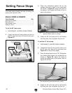
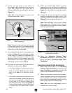
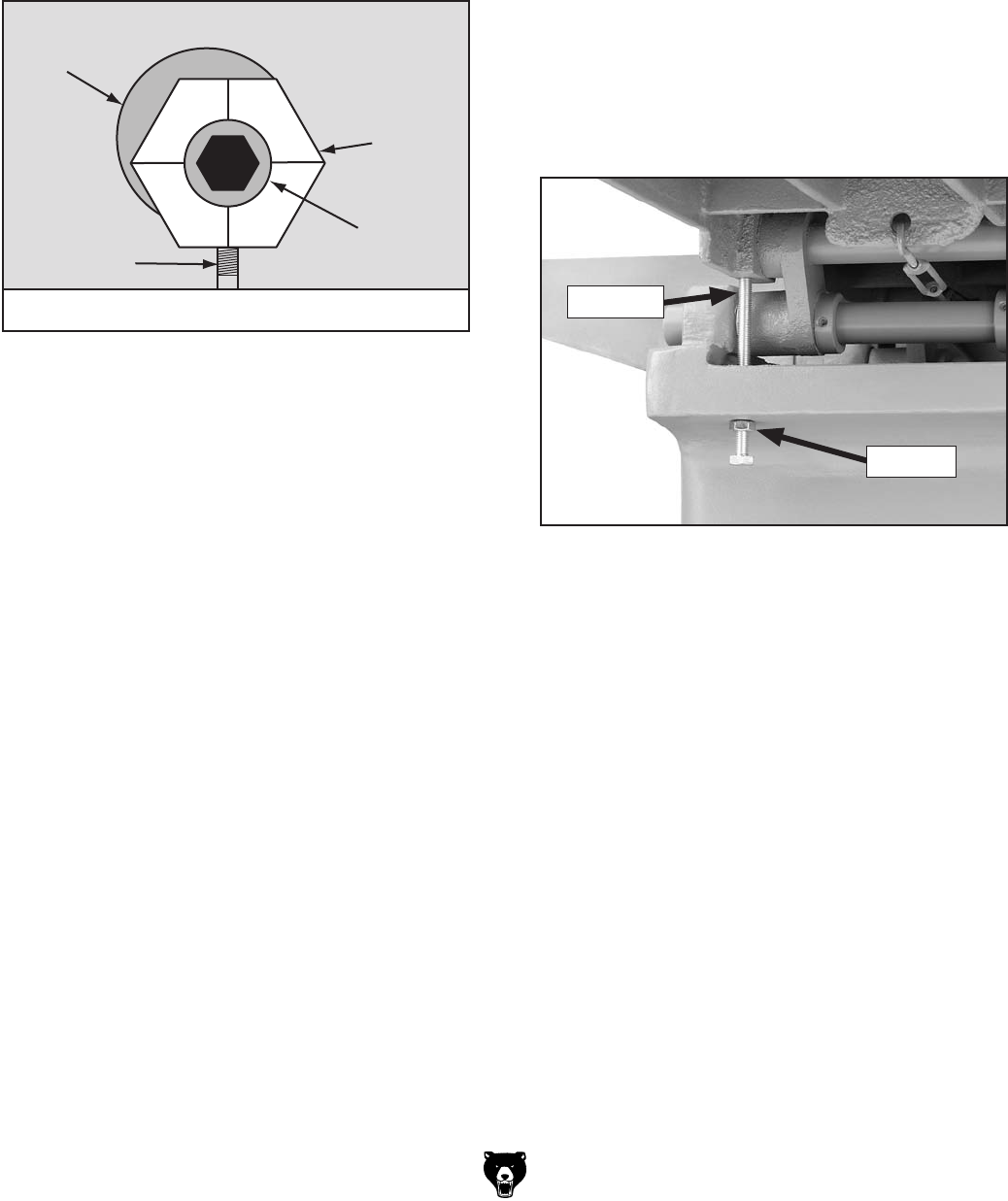
Figure 71
Note: Both of these screws are used to lock
the adjustment bolt in place.
8Vb
6Y_jhibZci
7dai
8Ve
HXgZl
HZiHXgZl
IVWaZ
Figure 71.
Note: The goal of the next step is to bring the
outfeed table parallel to the cutterhead body
from front-to-back by raising or lowering the
front corner of the outfeed table.
9.
Figure 71
Step 4
10.
Step 4
Step 11
Step 9
11.
Figure 71
12.
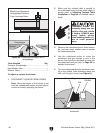
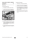
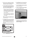
Figure 72
Note: When adjusted to the correct outfeed
table height, use the stop bolt for a conve-
nient method of ensuring the outfeed table is
set at the proper height.
13. Adjusting Outfeed Table
Parallelism
Adjusting Infeed Table
Parallelism
Adjusting Infeed Table Parallelism
1. Adjusting
Outfeed Table Parallelism
2.
Note: Make sure the straightedge is not in
contact with a knife or insert.
Figure 72.


