


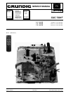

GRUNDIG Service1 - 2
Partie générale / General Section CUC 7301 F
The regulations and safety instructions shall be
valid as provided by the "Safety" Service Manual,
part number 72010-800.00, as well as the
respective national deviations.
Table of Contents
Page
General Section ................................... 1-1... 1-16
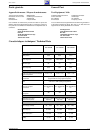
Technical Data ............................................................................. 1-3
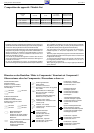
Module List................................................................................... 1-4
Safety Advice ............................................................................... 1-4
Hints to the Components ............................................................. 1-4
Hints to the Oscillograms ............................................................. 1-5
Circuit Diagram Symbols ............................................................. 1-6
Service Instructions (P 37-070).................................................. 1-11
Special and Service Functions................................................... 1-13
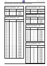
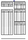
Tables of Norms and Channels ................................................. 1-15
Descriptions .........................................2-1... 2-10
1. Power Supply ........................................................................... 2-1
2. System Control ........................................................................ 2-3
3. TV Signal Processor TDA 8362 A ............................................ 2-4
3.1 Overview ................................................................................ 2-4
3.2 IF ........................................................................................ 2-4
3.3 CCVS-Signal ...................................................................... 2-4
3.4 External CCVS Signal ........................................................ 2-5
3.5 Sound IF............................................................................. 2-5
3.6 Luminance and Chrominance Signal ................................. 2-5
3.7 SECAM Signal Path
and Automatic PAL/SECAM Switching .............................. 2-6
3.8 RGB Signal Path ................................................................ 2-7
3.9 Generation of the Horizontal and Vertical Sync Signals .... 2-7
3.10 Line Oscillator .................................................................. 2-8
3.11 ϕ1-Phase Control ............................................................. 2-8
3.12 ϕ2-Phase Control ............................................................. 2-8
3.13 The Super Sandcastle SSC ............................................. 2-8
3.14 Setting of the Cut-Off Voltage .......................................... 2-8
3.15 The HDR Output Stage .................................................... 2-8
3.16 The Field Deflection Stage ............................................... 2-9
3.17 Non-Interlace Compensation with Teletext (optionally).... 2-9
3.18 Coinzidence ..................................................................... 2-9
Block Circuit Diagram............................................................. 2-10
Alignment ....................................................... 3-2
Chassis Board.............................................................................. 3-2
Layout of the PCBs
and Circuit Diagrams ......................... 4-1... 4-20
Tuner 29504-201.21 .................................................................... 4-1
Chassis Board.............................................................................. 4-3
General Circuit Diagram .............................................................. 4-9
Oscillograms .............................................................................. 4-14
Oscillogrammes CRT Panel....................................................... 4-16
CRT Panel 29305-022.14/.15 .................................................... 4-17
Tuner 29504-201.31 .................................................................. 4-19
Spare Parts List .................................. 5-1... 5-13
GB
F
II y a lieu d'observer les recommandations et les
prescriptions de sécurité de I'Instruction de Ser-
vice "Sécurité" Réf. N° 72010-800.00 ainsi que
les prescriptions spécifiques à chaque pays!
Sommaire
Page
Partie générale .................................... 1-1... 1-16
Caractéristiques techniques........................................................ .1-3
Composition des appareils........................................................... 1-4
Informations sur la sécurité .......................................................... 1-4
Observaciones sobre los componentes ....................................... 1-4
Indications pour les oscillogrammes ............................................ 1-5
Symboles schéma........................................................................ 1-6
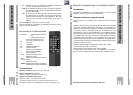
Eléments de commande (P 37-070) .......................................... 1-11
Fonctions de service et fonctions spéciales............................... 1-13
Tableaux des normes et des canaux ........................................ 1-15
Description des circuits ...................... 2-1... 2-10
1. Le C.I. Alimentation.................................................................. 2-1
2. Le système de commande ....................................................... 2-3
3. Le processeur de signal TV TDA 8362 A ................................. 2-4
3.1 Généralité........................................................................... 2-4
3.2 Circuit FI ............................................................................. 2-4
3.3 Le signal vidéo composite FBAS ....................................... 2-4
3.4 Le signal vidéo composite FBAS externe .......................... 2-5
3.5 Le signal FI audio ............................................................... 2-5
3.6 Les signaux de luminance et de chrominance ................... 2-5
3.7 Le signal SECAM et la commutation automatique
PAL-SECAM ...................................................................... 2-6
3.8 Le cheminement du signal RVB ......................................... 2-7
3.9 Génération des signaux de synchro horizontale et verticale ..... 2-7
3.10 L'oscillateur ligne.............................................................. 2-8
3.11 Le circuit de régulation ϕ1 ................................................ 2-8
3.12 Le circuit de régulation ϕ2 ................................................ 2-8
3.13 Le circuit de protection Super Sandcastle........................ 2-8
3.14 Le réglage de courant de Cut-Off..................................... 2-8
3.15 L’étage de puissance horizontale HDR ............................ 2-8
3.16 L’étage de déviation verticale........................................... 2-9
3.17 Compensation de non-entrelacement en télétexte (Option) ... 2-9
3.18 Le circuit de coïncidence.................................................. 2-9
Schéma synoptique................................................................ 2-10
Prescriptions d'alignement ........................... 3-1
C.I. Principal................................................................................. 3-1
Circuits impriméset
schémas électriques............................. 4-1... 4-20
Tuner 29504-201.21 .................................................................... 4-1
C.I. Principal................................................................................. 4-3
Schéma synoptique général ........................................................ 4-9
Oscillogrammes ......................................................................... 4-14
Oscillogrammes du C.I. Tube .................................................... 4-16
C.I. Tube 29305-022.14/.15 ...................................................... 4-17
Tuner 29504-201.31 .................................................................. 4-19
Liste de pièces détachées .................... 5-1... 5-13