


CUC 7301 F
GRUNDIG Service
2 - 5
Description des circuits / Circuit Description
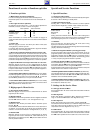
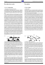
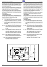
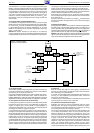
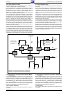
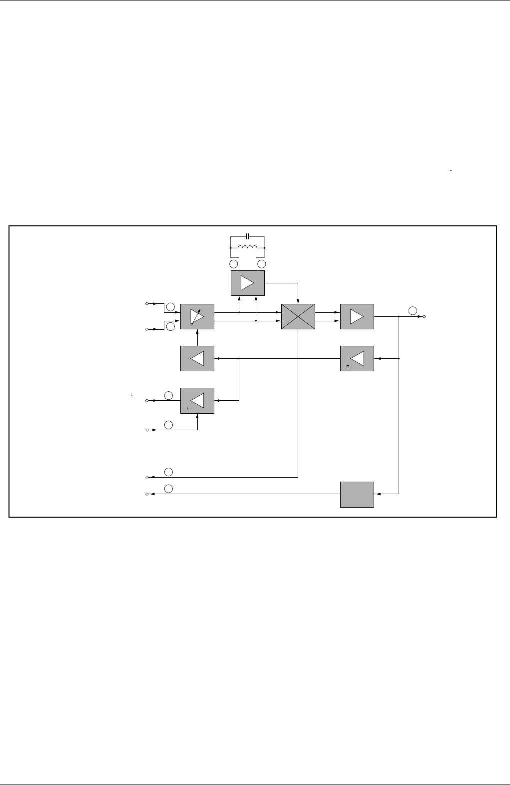
Bild ZF und Demodulation
Vision IF and Demodulation
FBAS und Ton
Ausgang
CCVS and Sound
Output
F130
ZF vom Tuner
IF from Tuner
U
für denTuner
for the Tuner
U
RV
vom Prozessor
from Processor
AFC
Koinzidenz
Coincidence
Sync
Detector
TDA8362A
~
45
46
2 3
47
49
9
4
7
~
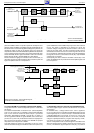
via le transistor CT110 et C2807 (Option) il est appliqué comme signal
FBAS
SC
au décodeur télétexte IC2810-(8) et via les transistors CT963
et CT962 à l’embase péritélévision Pin 19. Par ailleurs il est disponible
au commutateur de signal de source IC150-(13) comme signal vidéo
composite FBAS. La deuxième entrée du commutateur de signal de
source Pin 15 est reliée à la prise péritélévision Pin 20. A l’IC150-(16)
s’effectue le choix du microprocesseur IC850-(12), tension U
VQ,
tran-
sistor CT840, à savoir si c’est le signal du tuner ou le signal externe qui
doit être traité.
3.4 Le signal vidéo composite FBAS externe
Au commutateur de signal de source de l’IC150-(15) se tient un signal
FBAS externe provenant de l’embase péritélévision ou le signal FBAS-
HF. La tension U
VQ
à l’IC150-(16) détermine quel signal doit être traité,
le signal FBAS provenant de l’embase péritélévision ou le signal
FBAS-HF. Pour mémoire: IC150-(16) "Bas" = signal interne; IC150-(16)
"Haut" = signal externe.
Attention: Si l'option "Decoder On" est activée, le TV s'attend à
recevoir un signal en provenance de l'embase péritélévision.Néanmoins
le signal FBAS du tuner peut être mesuré à la sortie Pin 19 de l'embase.
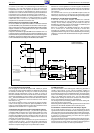
3.5 Le signal FI audio
Après le filtre céramique F926 le signal son est soumis à l'IC150-(5) à
une tension continue pour la commande du volume. La démodulation
est effectuée par une boucle de phase PLL.
D’une part le signal BF démodulé et non régulé est extrait de l’IC150-(1),
amplifié dans le circuit de transistors CT917, CT916 et transmis vers
l’embase péritélévision. D’autre part le signal BF démodulé et régulé est
disponible à l’IC150-(50) pour être transmis vers l’étage BF IC TDA 7233.
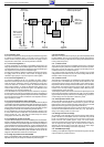
3.6 Les signaux de luminance et de chrominance
Le calibrage et la régulation sont effectués automatiquement pendant
la période de retour trame et ligne. Une modification du réglage des
signaux est obtenue par le courant positif ou négatif appliqué au
condensateur d’intégration CC177 de l’IC150-(12). Pendant la période
de balayage la tension de réglage est clampée.
Le signal de luminance traverse un réjecteur couleur intégré dans l’IC.
Une ligne à retard également câblée dans l’IC compense les écarts de
temps de propagation entre le signal de luminance et de chrominance.
Ensuite l’amélioration des transitions couleur (Peaking) est également
réalisée dans ce circuit. A cet effet on accentue les flancs ascendants
et descendants du signal Y. On extrait le signal chroma du signal vidéo
composite FBAS dans le filtre chroma interne. Un circuit de régulation
ajuste l’amplitude du signal vidéo pour le limiteur chroma et le réglage
chroma. Le signal chroma qui en résulte est dirigé sur le démodulateur
couleur. Le Burst issu du signal chroma synchronise la fréquence et la
sound signal is separated from the CCVS signal. After the transistor
CT921 and the sound trap F923 and F924 the signal path divides.
Via the transistor CT110 and IC2807 (optionally) it is fed through to the
videotext decoder IC2810-(8) as FBAS
SC
signal, and via the transistors
CT963, CT962 it is supplied to the Scart socket pin 19.
At the signal source switch IC150-(13), the signal is present as FBAS.
The second input of the signal source switch Pin 15 is connected to the
Scart socket pin 20.
At IC150-(16), the processor IC850-(12), voltage U
VQ
, transistor CT840
decides as to whether the signal from the tuner or the external signal
is processed.
3.4 External CCVS Signal
At the signal source switch IC150-(15) either an external CCVS signal from
the Scart socket or the HF-CCVS signal is present. The voltage U
VQ
at
IC150-(16) decides which signal shall be passed on, the CCVS signal from
the Scart socket or else the HF-CCVS signal. IC150-(16) "Low", the internal
signal is selected; IC150-(16) "High", the external signal is passed on.
Attention: If the option "Decoder On" has been selected the TV expects the
signal to come from the Scart socket. However the CCVS signal from the
tuner can be measured at output Pin 19 of the Scart socket.
3.5 Sound IF
After the ceramic filter F926, the sound signal is superimposed at
IC150-(5) on a direct voltage for setting the volume level. Demodula-
tion is effected by a PLL demodulator.
In one path, the demodulated and uncontrolled AF signal is fed out at
IC150-(1), it is then amplified by the transistors CT917, CT916 and
passed on to the Scart socket.
In another path, the demodulated and controlled AF signal is present
at IC150-(50) and is fed to the AF-IC TDA 7233.
3.6 Luminance and Chrominance Signal
Calibration and control is effected automatically during the frame
blanking period. The signals are adjusted by a positive or negative
current entering the integration capacitor CC177 at IC150-(12). During
the scanning period the control voltage is clamped.
The luminance signal passes though the colour trap integrated in the
IC. The delay line provided in the IC is used to correct delay time
differences between the luminance and chrominance signal. The
colour transient improvement (peaking) which follows is also realized
in this IC. For this, the steepness of the leading and trailing edges of the
Y-signal is improved. The internal chroma filter separates the
chrominance signal from the CCVS signal. A control circuit adjusts the
amplitude of the colour signal for the chroma limiter and chroma
control. The resulting chroma signal is passed on to the colour
demodulator. From this chroma signal, the burst is separated which is
used to synchronise the colour oscillator in phase and frequency. The