


CUC 7301 F
GRUNDIG Service
2 - 9
Description des circuits / Circuit Description
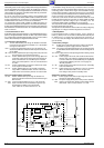
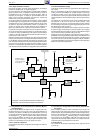
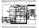
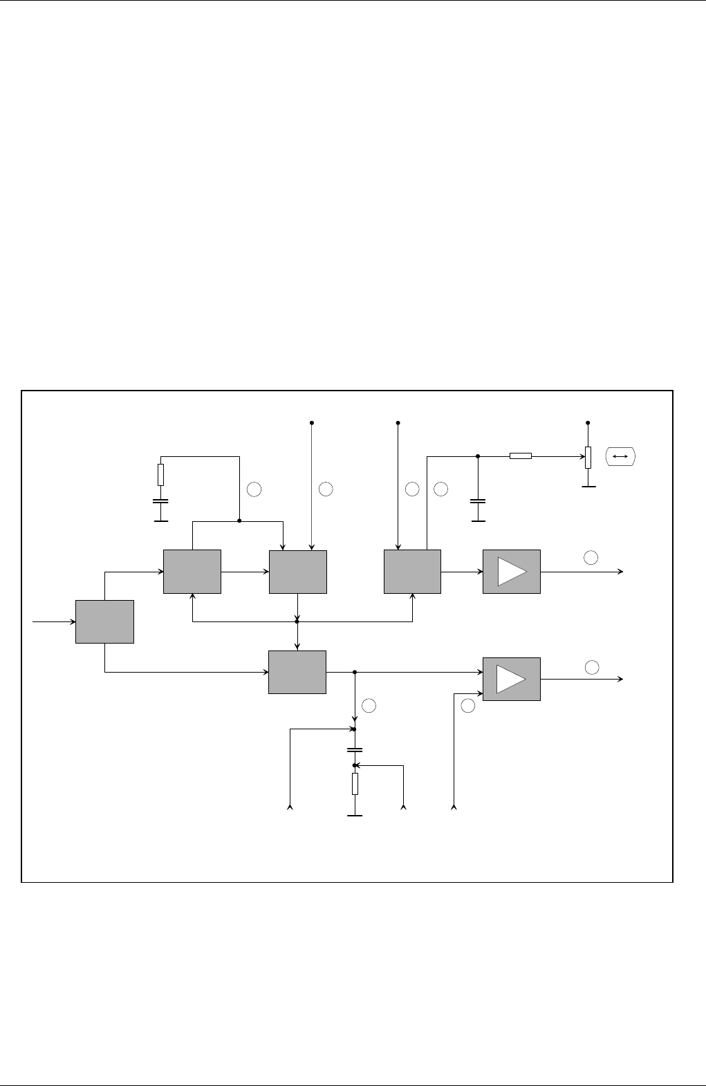
Zeilenoszillator
Line Oscillator
25 Hz
FBAS
CCVS
Amplitudensieb
Sync Separator
ϕ
1
Zeilenzähler
Line Counter
V-Sync
H-Sync
ϕ
2
HDR
+
-
VDR
SB VFB
40 36
Enable Oszillator
Enable Oscillator
38 39
Regelzeitkonstante
für die
ϕ
1-Regelung
Regelzeit-
konstante für die
ϕ
2-Regelung
Control Time Constant
for
ϕ
2-Control
Flyback
37
43 42
44
Control Time Constant
for
ϕ
1-Control
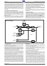
Horizontal- und Vertikal-Synchronisation und Ablenkung
Horizontal- and Vertical Synchronisation and Deflection
3.16 L’étage de déviation verticale
Dans cette conception de circuit intégré le générateur de déviation
verticale est remplacé par un compteur de lignes.
Si aucune impulsion de synchronisation n’est disponible, l’oscillateur
lignes fonctionne à vide. „L’oscillateur vertical“ est dérivé à partir de
l’oscillateur lignes par le comptage du nombre de lignes. Après le
décompte de 312 lignes, un signal de synchronisation trame est
délivré. Ainsi la déviation horizontale aussi bien que verticale est
réalisée sans aucune synchronisation externe.
En cas de réception d’un signal de synchronisation, c’est tout d’abord
l’oscillateur lignes qui est synchronisé. Le compteur de lignes délivre
également dans ce cas un signal de déviation verticale. Si par contre
on obtient un signal de synchronisation verticale, le générateur de
signaux en dents de scie n’est plus déclenché par le compteur de
lignes mais directement par le signal de synchronisation verticale.
Le générateur de signaux en dents de scie est constitué d’une source
de courant constant qui charge et décharge un condensateur externe.
Le temps de charge est déterminé par le signal de synchronisation
verticale. La dent de scie de déviation verticale peut être mesurée au
condensateur C158, IC150-(43).
Afin de pouvoir effectuer les réglages du tube dans l’étage final vertical
IC400 il y a lieu d'intervenir sur le signal de déviation en dents de scie.
La modification doit être effectuée avant l’étage de puissance verti-
cale. A cet effet on dispose à l’IC150-(42) d’un signal d’asservissement
en provenance de l’IC400 pour l’étage de contre-réaction. De façon
identique à un amplificateur opérationnel relié à une entrée négative,
cette technique permet d’effectuer le réglage des divers paramètres
3.17 Compensation de non-entrelacement en télétexte (Modula-
tion 25Hz) Option
Lorsqu’un signal télétexte est affiché à l’écran, ce signal saute cons-
tamment d’une ligne vers le bas et vers le haut (signal télétexte non
entrelacé). Pour éviter ce sautillement, l’IC télétexte 2810-(13) envoie
un signal de commutation de 25Hz à l’IC150-(43). Depuis cette tension
de commutation U
25Hz
on dérive un faible courant continu permanent
pour le signal de déviation en dents de scie. Ainsi la première demi-
image est décalée vers le haut. Les lignes paires et impaires seront
inscrites en superposition les unes par rapport aux autres.
3.18 Le circuit de coïncidence
L’information de coïncidence est générée dans l’étage FI et délivrée à
l’IC150-(4).
3.16 The Field Deflection Stage
In this circuit concept, the field sync generator has been replaced by a
line counter.
When no synchronising signals are received the line oscillator is free
running. From this line oscillator the "vertical oscillator" is derived by
counting the number of lines. After having counted 312 lines, the
counter feeds out a field sync signal so that the horizontal and also the
vertical deflection is achieved without using an external synchronising
signal.
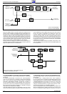
On reception of a synchronising signal, the line oscillator will first be
synchronised. In this case too, the line counter supplies a field
deflection signal. As soon as a field synchronising signal is obtained
the saw-tooth generator will no longer be triggered by the line counter
but directly by the field sync signal.
The saw-tooth generator is made up of a constant current source which
is used to charge and discharge an external capacitor. The charging
period is determined by the field sync signal. The field deflection signal
can be measured at the capacitor C158, IC150-(43).
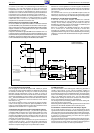
Adjustment of the field amplitude at the field output stage IC400 is
possible by influencing the field saw-tooth voltage. This alteration must
be carried out before the field output stage. For this, a feedback signal
from IC400 is present at IC150-(42) for negative feedback. Similar to
an operational amplifier connected to the negative input, this technique
allows to set the desired parameters.
3.17 Non-Interlace Compensation with Teletext (25Hz Modula-
tion) Option
When a teletext (videotext) signal is displayed on the screen, the
teletext signal would continuously change by one line upwards and
downwards (non-interlaced teletext signal). To avoid the signal chang-
ing the line, the teletext IC2810-(13) supplies a 25Hz switching signal
to IC150-(43). From this U
25Hz
switching voltage, a small DC voltage
offset is derived for the deflection saw-tooth. This offset effects an
upward shift of the first half-field so that the even-numbered and odd-
numbered lines are superimposed on each other.
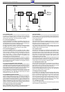
3.18 Coincidence
The coincidence information is generated in the IF stage and fed out
on IC150-(4).