


CUC 7301 F
GRUNDIG Service
2 - 7
Description des circuits / Circuit Description
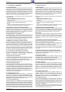
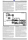
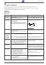
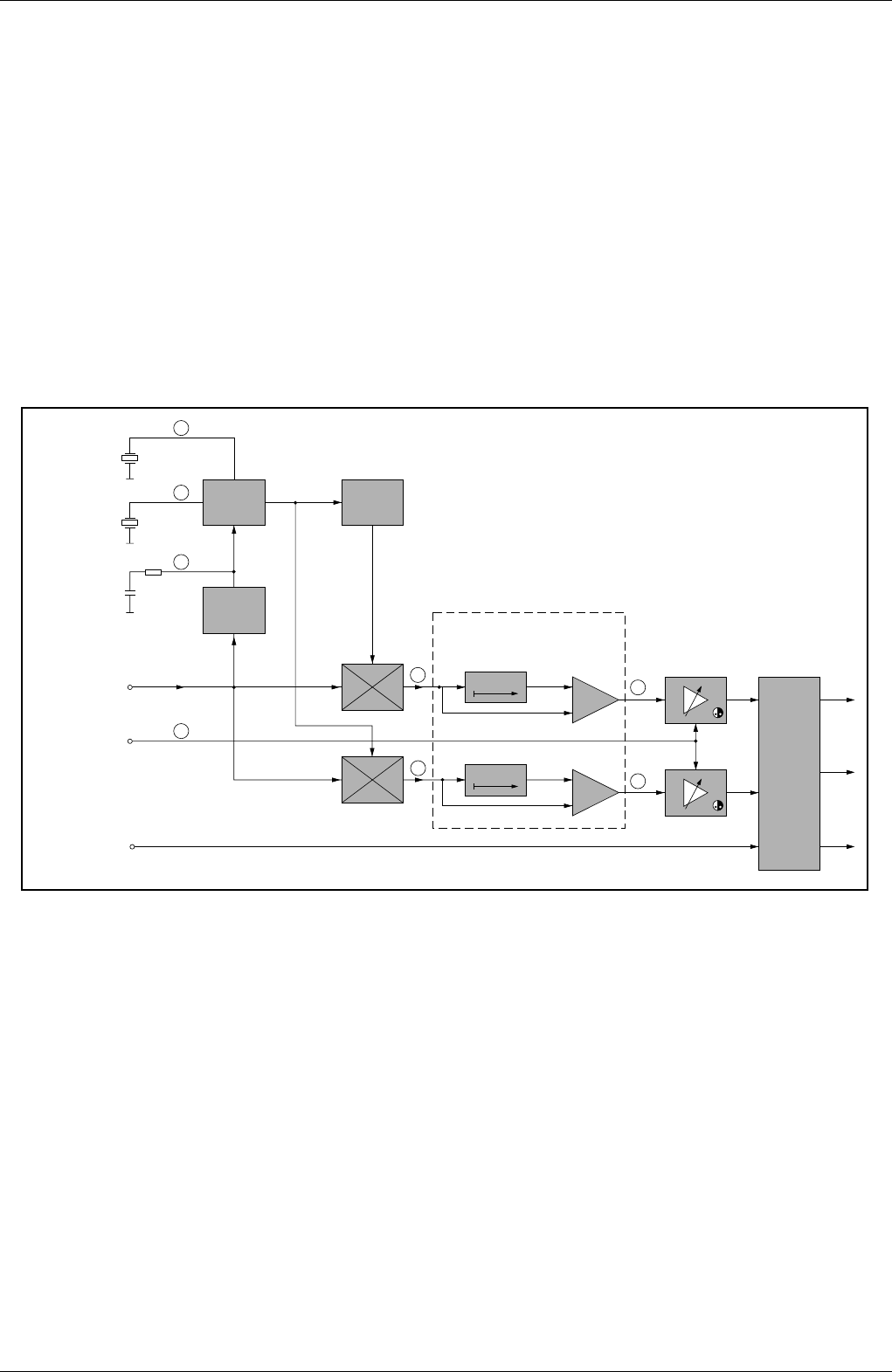
Chroma-Signal
35
Farbkontrast vom
Prozessor
Colour Contrast
from Processor
Luminanzsignal
Luminance Signal
Burst
PLL
(R-Y)
(B-Y)
(R-Y)
(B-Y)
Delay
Delay
RGB
Matrix
R
G
BY
+
+
33
26
30
31
4,43
MHz
4,43
MHz
34
3,58
MHz
Farb-Oszillator
Colour Oscillator
29
28
H/2
PAL-Schalter
PAL Switch
TDA4662
TDA4665 (OIRT/FR)
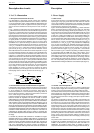
Farbdemodulation
Colour Demodulation
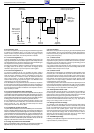
sur 3,5V CC (1,5V en PAL). Les sorties des signaux de différence de
l'IC150-(30), -(31) sont ainsi bloquées. Et l'IC110 peut fournir les
composantes R-Y et B-Y. Ces signaux de différence sont ensuite
renvoyées vers l'IC150 par l'intermédiaire des circuits de lignes à
retard CIC105. La suite du cheminement des signaux est décrite dans
le paragraphe 3,6 "Les signaux de luminance et de chrominance".
Par le niveau de courant continu de 3,5V disponible à l'IC110-(10) en
réception SECAM, le transistor T117 devient conducteur, U
PAL
passe
à l'état "Bas" (PAL = "Haut") et le µP IC850-(30) peut identifier la
réception PAL ou SECAM en recherche ATS.
Platine auxiliaire de commutation forcée SECAM
En cas de conditions de réception défavorables, le commutateur automati-
que PAL/SECAM ne peut pas identifier correctement la norme correspon-
dante. C'est pourquoi on câble sur les appareils SECAM une platine auxiliaire
équipée en fonction de la configuration de l'IC150 pour la commutation
forcée SECAM (CT117, CT120).
Lorsque l'IC110 identifie un signal SECAM les deux transistors CT117 et
CT120 sont saturés. CT120 tire l'IC150-(33) à la masse et interdit une erreur
d'asservissement en phase de l'oscillateur. Si l'IC110 a commuté les signaux
de différence, la tension de commande U
PAL
bloque à nouveau le transistor
CT120 et l'identification automatique PAL-SECAM est ainsi rétablie.
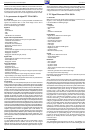
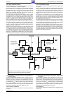
3.8 Le cheminement du signal RVB
Pour le réglage du contraste des signaux RVB, l’IC850-(31) produit
une tension de réglage variable destinée à l’amplificateur de réglage
du contraste à l'IC150-(25). Du fait qu’un courant de faisceau trop
important pourrait endommager le tube, l’IC limite ce courant de
faisceau.La limitation interne du courant de faisceau crête est réalisée
dans l’étage de limitation du niveau du blanc. Si le signal RVB excède
2,6V
CC
, la fonction de limitation du niveau du blanc intervient et diminue
le contraste. La limitation du courant de faisceaux crête externe
intervient à env. 2V
CC
.
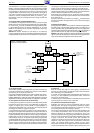
Pour le frein de faisceau moyen, les tensions de réglage sont dimi-
nuées à l'IC150-(25) pour le contraste. Après l’amplificateur de lumi-
nosité, les signaux RVB quittent l’IC150 pour être acheminés vers les
amplificateurs de cathode du C.I. support de tube.
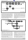
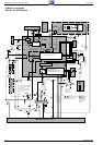
3.9 Génération des signaux de synchro horizontale et verticale
Le processeur de signal TV IC150-(13), -(15) est relié au signal vidéo
composite FBAS provenant de la FI et de l’embase EURO-AV. Après
un réjecteur couleur interne dans lequel l’information couleur est
extraite du signal FBAS, le signal Y est divisé en deux voies. Sur l’une
le signal est disponible pour la suite du traitement et sur l’autre il est
acheminé vers le séparateur synchro.
Le séparateur synchro produit l’impulsion de synchro horizontale et
verticale à partir du signal Y. Le signal de synchro horizontale est
envoyé vers le circuit de régulation ϕ1, le signal de synchro verticale
démarre le compteur de lignes pour la synchronisation verticale.
blocked. IC110 now supplies the R-Y and B-Y signals. The difference
signals are returned to IC150 via the delay line CIC105. The following
path of these signals is described unter 3.6 "Luminance and Chromi-
nance Signal".
The 3.5V DC level at IC110-(10) on SECAM reception causes the
transistor T117 to turn on, U
PAL
changes to "Low" (PAL="High") and µP
IC850-(30) is able to identify PAL or SECAM during the ATS operation.
Sub-Panel for Forced Switching to SECAM
In the case of unfavourable reception conditions the automatic
PAL/SECAM switching IC cannot identify the respective standard
correctly. For this reason, depending on the version of IC150, the
SECAM colour television receivers are fitted with an additional panel
for forced switching to SECAM (CT117, CT120).
When IC110 identifies the SECAM standard, the two transistors
CT117, CT120 turn on. CT120 pulls IC150-(33) to chassis thus
preventing the oscillator from locking in wrongly. After IC110 has
supplied the difference signals, CT120 is switched off by the switching
voltage U
PAL
so that the PAL-SECAM standards are again automatical-
ly identified.
3.8 RGB Signal Path
For contrast control of the RGB signals, IC850-(31) generates a
variable control voltage for the contrast controlling amplifier at
IC150-(25). Because too high a beam current may cause damage to
the picture tube, the beam current is limited by this IC. The internal peak
beam current limiting function is carried out in the peak white limiting
stage. If the RGB signal exceeds 2.6V
pp
, the peak white limiting
function starts working and reduces the contrast. The external peak
beam current limiting threshold is 2V
pp
approximately.
The average beam current limiting function reduces the setting volt-
ages at IC150-(25) for the contrast.
After the brightness amplifier, the RGB signals leave the IC150 and are
passed on to the cathode amplifiers on the CRT base panel.
3.9 Generation of the Horizontal and Vertical Sync Signals
The TV signal processor IC150-(13), -(15) is connected to the CCVS
signal from the IF and from the EURO-AV socket. Following an internal
colour trap where the colour information is filtered off the CCVS signal,
the resulting Y-signal now divides into two paths. In one path the signal
is passed on for further processing, and in the other, the signal is
applied to the sync separator.
The sync separator produces the horizontal and the vertical synchron-
ising pulses from the Y-signal. The horizontal synchronising signal is
passed on to the ϕ1 phase control, the vertical synchronising pulse is
used to start the line counter for vertical synchronisation.