


SKU 04019 PAGE 10
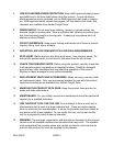
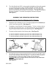
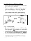
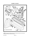
5. Once the centering procedure is completed, make sure to tighten the two Socket
Screws (part #26) to secure the tool bit in place. (See Figure F.)
TAILSTOCK
CENTER
(#50)
SOCKET SCREW
(#26)
TIP OF TOOL BIT
(NOT INCLUDED)
IF NEEDED,
INSERT
SHIMS
(NOT INCLUDED)
HERE
TAILSTOCK ASSY.
(#45)
TOOL HOLDER
(#24)
FIGURE F
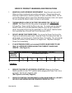
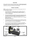
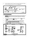
To Adjust The Spindle Speed:
1. CAUTION: Always turn the Power Switch (part #2) of its’ “OFF” position and
unplug the Mini Bench Lathe from its’ electrical outlet before performing
this procedure.
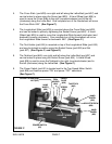
2. The Mini Bench Lathe features three different Drive Belts: the Short Drive Belt,
the Medium Drive Belt, and the Long Drive Belt.
3. The Short Drive Belt is mounted on the Idler (part #6) and the Motor Pulley
(part #11). Do not adjust or reposition this Drive Belt. (See Figure G.)
4. The Medium and Long Drive Belts are accessory Belts, and both are used to
adjust the spindle speed of the Mini Bench Lathe. (See Figure G.)
A = OUTER BELT POSITION
B = INNER BELT POSITION
A
B
A
B
MOTOR PULLEY
(#11)
IDLER
(#6)
SPINDLE PULLEY
(#16)
SHORT
DRIVE
BELT
MEDIUM
DRIVE
BELT
LONG
DRIVE
BELT
FRONT VIEW SIDE VIEWSIDE VIEW
FIGURE G