


SKU 04019 PAGE 7
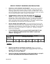
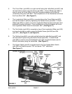
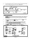
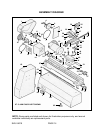
5. The Cross Slide (part #28) runs right and left along the Lathe Bed (part #57) and
can be locked in place using the Screw (part #29). A Hand Wheel (part #36) is
used to move the Cross Slide to the right (counterclockwise) and to the left
(clockwise) along the Lathe Bed. One complete turn of the Handwheel will move
the Cross Slide .065”. (See Figure C.)
6. The Longitudinal Slide (part #35) is mounted above the Cross Slide (part #28)
and can be locked in place by tightening the Socket Screw (part #40). A Hand
Wheel (part #36) is used to move the Longitudinal Slide forward (clockwise) and
backward (counter clockwise). One complete turn of the Handwheel will move
the Longitudinal Slide forward or backward .065”. (See Figure C.)
7. The Tool Holder (part #24) is mounted on top of the Longitudinal Slide (part #35)
and may be locked in position using the Socket Screw (part #26) and Nut
(part #27). (See Figure C, and Figure E.)
8. The Tailstock (part #45) runs right and left along the Lathe Bed (part #57) and
can be locked in place using the Socket Screw (part #54). A Hand Wheel
(part #36) is used to move the Tailstock to the right (counterclockwise) and to
the left (clockwise) along the Lathe Bed. (See Figure C.)
9. The Power Switch (part #2) is located next to the Two Speed Motor Switch
(part #66) and features power “ON” and power “OFF” selections.
(See Figure C.)
POWER SWITCH
(#2)
TAILSTOCK
(#45)
SOCKET SCREW
(#54)
HAND
WHEEL
(#36)
HAND
WHEEL
(#36)
CROSS
SLIDE
(#28)
SCREW
(#29)
LONGITUDINAL SLIDE
(#35)
SOCKET SCREW
(#40)
HAND
WHEEL
(#36)
TOOL
HOLDER
(#24)
SOCKET SCREW (#26)
NUT (#27)
FIGURE C