


UNPACKING
When unpacking, check to make sure all the parts shown on the Parts Lists on page 13
are included. If any parts are missing or broken, please call Harbor Freight Tools at the
number shown on the cover of this manual as soon as possible.
PRODUCT FEATURES
NOTE: For additional references to the parts listed in the following pages, refer to the
Assembly Diagram on page 14.
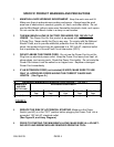
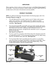
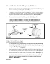
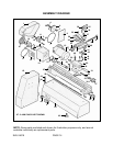
1. The Lathe Bed (part #57) is made of cast iron and is T-ribbed, which ensures
rigidity and low vibration. The Headstock (part #14), Tailstock (part #45),
Carriage Assembly (part #35), and Lead Screw (part #58) are mounted on the
Lathe Bed. (See Figure B.)
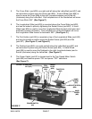
2. The 3-Jaw Chuck (part #67) is reversible, giving you larger capacity, and can be
used as either internal or external jaws. The workpiece is automatically centered
when held in the 3-Jaw Chuck. Workpieces with a diameter of up to 1” are
gripped with the internal jaws. Workpieces with a diameter of up to 2” are gripped
with the external jaws.
(See Figure B, and Figure D.)
3. The Cover (part #1) is mounted on the left hand side of the Headstock (part #14)
and Lathe Bed (part #57). The Cover protects the Motor (part #12), Motor Pulley
(part #11), and Spindle Pulley (part #16). (See Figure B.)
4. The Two Speed Motor Switch (part #66) allows the operator to run the Motor
(part #12) at either Low Speed (3,850 RPM) or High Speed (5,490 RPM). When
turning materials with a larger diameter, use the Low Speed setting. When
turning harder materials, use the Low Speed setting.
SKU 04019 PAGE 6
TWO SPEED
MOTOR SWITCH
(#66)
COVER
(#1)
3-JAW CHUCK (#67)
LATHE BED
(#57)
HEADSTOCK
(#14)
TAILSTOCK
(#45)
LEAD SCREW
(#58)
FIGURE B