


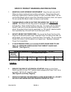
SKU 04019 PAGE 9
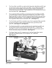
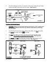
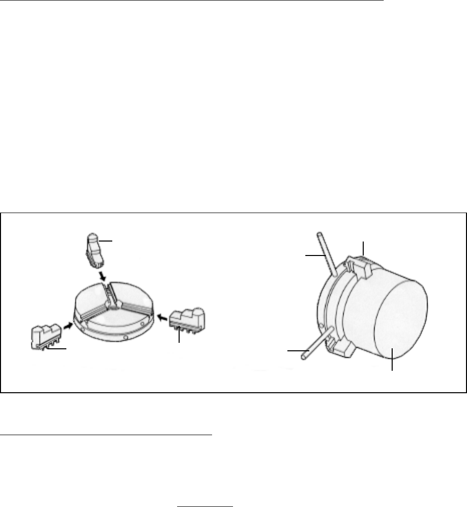
To Assemble The 3-Jaw Chuck For A Workpiece Up To 2” Diameter:
1. Workpieces with a diameter of up to 2” should be gripped with the external jaws
of the 3-Jaw Chuck (part #67). (See Figure E.)
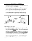
2. If necessary, reverse the jaws for external gripping. To do so, unscrew, remove,
and clean each of the three jaws. Turn the knurled tension ring until the begin-
ning of the spiral thread comes to the respective groove. (See Figure D.)
3. The jaws are then inserted in the following order: (See Figure D.)
A. Jaw #1 is inserted in reverse in groove #3, then rotate the tension ring.
B. Jaw #2 is inserted in reverse in groove #2, then rotate the tenson ring.
C. Jaw #3 is inserted in in reverse in groove #1, then rotate the tension ring.
1
3
2
2
31
JAW
JAW
JAW
3-JAW CHUCK
(#67)
PIN
PIN
WORKPIECE
CAPACITY
UP TO
2”
FIGURE E
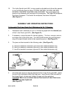
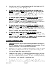
To Adjust The Tool Bit Center Height:
1. The tip of the tool bit (not included) must coincide exactly with the center of the
Tailstock Center (part #50). If the tip of the tool bit is not positioned properly, the
correct cutting dimensions cannot be obtained. Also, the tip of the tool bit may be
damaged. (See Figure F, next page.)
2. Place the tool bit in the Lathe’s Tool Holder (part #24), but do not yet tighten the
two Socket Screws (part #26) which clamp the tool bit in place. (See Figure F.)
3. Have several small, thin, metal, shims (not included) on hand. (See Figure F.)
4. Adjust the tip of the tool bit to the center of the Tailstock Center (part #50). If
necessary, insert the shim(s) under the tool bit in order to obtain the proper
centering. (See Figure F.)