


Page 12 For technical questions, please call 1-800-444-3353. SKU 44506
MAINTENANCE AND
SERVICING
Procedures not specically
explained in this manual must
be performed only by a qualied
technician.
TO PREVENT
SERIOUS INJURY
FROM ACCIDENTAL
OPERATION:
Turn the Power Switch of the tool
to its “OFF” position and unplug
the tool from its electrical outlet
before performing any
inspection, maintenance, or
cleaning procedures.
TO PREVENT SERIOUS INJURY
FROM TOOL FAILURE:
Do not use damaged equipment.
If abnormal noise or vibration
occurs, have the problem
corrected before further use.
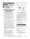
Cleaning, Maintenance, and
Lubrication
BEFORE EACH USE,1. inspect the
general condition of the tool. Check for
loose hardware, misalignment or binding
of moving parts, cracked or broken parts,
damaged electrical wiring, and any
other condition that may affect its safe
operation.
AFTER USE,2. wipe external surfaces of
the tool with clean cloth.
3. WARNING! If the supply cord of
this power tool is damaged, it must be
replaced only by a qualied service
technician.
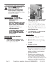
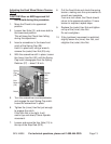
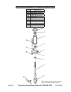
Removing the Chuck and Spindle Shaft
During this procedure, refer to the Chuck
and Spindle Assembly Drawing.
Pull the Feed Wheel counterclockwise
1.
and hold the Chuck at a depth of three
inches.
Align the key holes in the Spindle Shaft
2.
(B7) and the Quill Tube (B3) by turning
the Chuck by hand.
Insert a Wedge Drift Key (not supplied) 3.
into the key holes.
Place a bundled cloth or basket below
4.
the Chuck to catch it when it falls.
Lightly tap the Wedge Drift Key with a
rubber mallet until the Spindle Shaft falls
out of the Quill Tube.
Installing the Chuck and Spindle Shaft
Using a clean cloth, wipe the tapered 1.
surfaces on the Spindle Shaft (B7).
Slide the Spindle Shaft and Chuck 2.
assembly up and into the Quill Tube
(B3).
At the same time, turn the assembly until
the rectangular end of the Spindle Shaft
slips into the notch on the Quill Tube.
WARNING! In the previous step, if the
Spindle Shaft is not properly set in
the Quill Tube notch, it may y out
during operation.
Loosen the Lock Handle Support (C2) 3.
and raise the Table (C7) about three
inches below the Chuck.
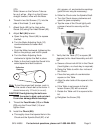
Turn the Chuck sleeve clockwise to open 4.
the jaws completely.
Pull the Feed Knob counterclockwise 5.
and force the Chuck against the Table
until the Spindle Shaft is secure.