


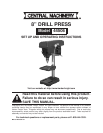

Page 8 For technical questions, please call 1-800-444-3353. SKU 44506
SPECIFICATIONS
Electrical Input 120 V~, 60 Hz, 1/3 HP (3.6 A)
Motor Speed 1750 RPM (No Load)
Spindle Speeds 620, 1100, 1720, 2340, and 3100 RPM
Spindle Stroke 2”
Base 11-1/8” x 7”; Slot: 9/16”
Throat Depth 4” (of 8” swing)
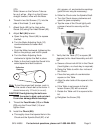
Chuck 1/2”
Table Rotation 360°; Tilt: 45° (left and right)
Table Size 6-5/8” x 6-3/8”
Table Slot 5/8”
E105017
UNPACKING
When unpacking, make sure that the
item is intact and undamaged. If any parts
are missing or broken, please call Harbor
Freight Tools at 1-800-444-3353 as soon as
possible.
Assembly hardware is located in
separate bags/boxes. Each contains the
necessary parts for each assembly step.
Remove all packing and protective material
from the Drill Press components.
INSTRUCTIONS FOR PUTTING
INTO USE
Read the ENTIRE IMPORTANT
SAFETY INFORMATION
section at the beginning of this
manual including all text under
subheadings therein before set up
or use of this product.
TO PREVENT
SERIOUS INJURY
FROM ACCIDENTAL
OPERATION:
Turn the Power Switch of the tool
to its “OFF” position and unplug
the tool from its electrical outlet
before assembling or making any
adjustments to the tool.
Note: For additional information regarding the
parts listed in the following pages, refer
to the Assembly Diagram near the end of
this manual.
Assembly/Mounting
Note: Assembly hardware is located in
separate bags/boxes.
Position the 1. Base (C4) on a level and
sturdy table for mounting.
It is recommended to bolt the Base to the
table using appropriate hardware (not
supplied).
Place the
2. Support Tube (C3) on the
Base, aligning the mounting holes.
Insert three large Hex Screws (C5) into
3.
the mounting holes and tighten.
Install the 4. Table Support (C1), with
attached Table (C7), over the Support
Tube (C3) and slide it down. Hand
tighten the Lock Handle Support (C2).
CAUTION! Avoid injuries. The next step
involves lifting the Head Assembly
onto the Support Tube. The Head
Assembly is heavy. Have someone
help you lift this assembly into place.
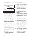
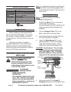
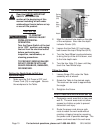
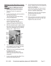
Set
Screws
(11)
Feed
Knob (12)
Guard (A5)
Knob
(A2)
Motor
Adjusting
Knob (10)
5. Using two people, lift the Head (1)
Assembly up and onto the Support Tube