


SKU 44506 For technical questions, please call 1-800-444-3353. Page 6
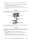
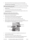
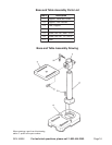
4. Install the Table Support (C1), with attached Table (C7), over the Support Tube (C3)
and slide it down. Hand Tighten the Lock Handle Support (C2).
CAUTION: Avoid injuries. The next step involves lifting the Head Assembly onto the
Support Tube. The Head Assembly is heavy. Have someone help you lift this assembly
into place.
5. Using two people, lift the Head (1) Assembly up and onto the Support Tube (C3).
Slide it down on the Column Tube as far as it will go. Align it so that it faces straight
forward, inline with the Base.
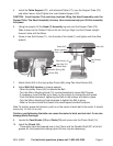
6. Screw in two Set Screws (11), into the side of the Head (1) and tighten with the Allen
wrench.
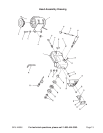
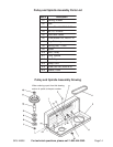
7. Attach Knob (A2) to the (top) pulley Guard (A5) using Pan Head Screw (A3).
8. Adjust Belt (A4) tension or change speeds.
- Open the pulley Guard (A5) to expose the Belt.
- Turn the Motor Adjusting Knob (10) counterclockwise to loosen Belt Tension.
- If necessary, move the Belt up or down on the pulleys to change the drill speed.
- Push the Motor backward, tightening the Belt on the pulleys, and hold in place.
- Turn the Motor Adjusting Knob clockwise to tighten the Belt in place.
- Refer to the chart inside the Guard lid to select speed and belt locations.
Note: To test the proper belt tension, push in on the center of each belt at its center. It should
move only 1/2 inch (in or out).
Caution: overtightening the belts can cause the motor to bind, and not start. It can also
damage Motor bearings.
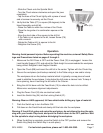
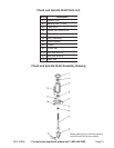
9. Locate the Feed Knobs (12) and Rods (13) and screw onto the Pinion Shaft (14).
10. Install the Chuck (B8).
- Thoroughly clean the tapered hole in the Chuck and the Spindle Shaft (B7) of all dirt,
grease, oil, and protective coatings (paint thinner may be necessary).
Set Screws
(11)
Feed Knob (12)
Chuck (B8)
Tension Spring (28)
Guard (A5)
Knob (A2)
Hex Nuts (31)
Feed Wheel Stop
Motor Adjusting
Knob (10)