


SKU 44506 For technical questions, please call 1-800-444-3353. Page 9
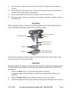
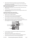
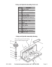
2. Slide the Spindle Shaft and Chuck assembly up and into the Quill Tube (B3).
At the same time, turn the assembly until the rectangular end of the Spindle Shaft
slips into the notch on the Quill Tube.
Warning: In the previous step, if the Spindle Shaft is not properly set in the Quill Tube
notch, it may fly out during operation.
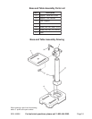
3. Loosen the Lock Handle Support (C2) and raise the Table (C7) about three inches
below the Chuck.
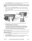
4. Turn the Chuck sleeve clockwise to open the jaws completely.
5. Pull the Feed Knob counterclockwise and force the Chuck against the Table until the
Spindle Shaft is secure.
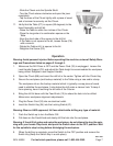
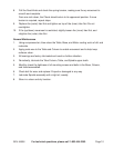
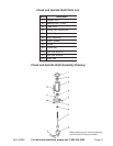
Adjusting the Feed Wheel Return Tension Spring
Caution: Wear a full face shield during this procedure.
1. Move the Chuck to its uppermost position.
2. Loosen Hex Nuts (31) and move both to the lowermost position.
This will keep the Chuck from falling during this adjustment.
3. Insert a screwdriver in the lower-front notch of the Spring Cap (29).
Hold it in place and, using a wrench, remove the (outer) Hex Nut (30) only.
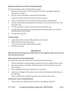
4. With the screwdriver still in place, loosen the (inner) Hex Nut (30) until the Spring Cap
notch disengages from the Spring Retainer (27) -- about 1/8 inch.
5. Turn the screwdriver counterclockwise and engage the next Spring Cap notch.
Leave the screwdriver in place.
6. Tighten the (inner) Hex Nut just enough to engage the notch.
If this Hex Nut is too tight, it will restrict (up and down) Chuck-Spindle movement.
7. Loosen and screw the Hex Nuts (31) to the top of the Stop Rod (B12).
Hex Nuts (30)
Spring Cap (29)
Notch
Hex Nuts (31)
Pointer (32)