


SKU 44836 PAGE 5
10. CAUTION: Some woods contain preservatives such as copper chromium arsenate
(CCA) which can be toxic. When drilling these materials extra care should be taken
to avoid inhalation and minimize skin contact.
11. ALLOW THE DRILL BIT TO SPIN UP TO FULL SPEED BEFORE DRILLING INTO
THE WORKPIECE. When turning off the Drill Press, allow the drill bit to spin down
and stop on its own. Do not press the drill bit against the workpiece to stop it.
12. DO NOT FORCE THE DRILL BIT INTO THE WORKPIECE WHEN DRILLING.
Apply moderate downward pressure, allowing the drill bit to cut without being forced.
13. NEVER ATTEMPT TO REMOVE MATERIAL STUCK IN THE MOVING PARTS OF
THE DRILL PRESS WHILE THE DRILL PRESS IS PLUGGED IN AND RUNNING.
14. THE DRILL BIT WILL BECOME HOT WHILE DRILLING. Allow the drill bit to
completely cool before touching.
15. WHENEVER POSSIBLE, USE CLAMPS OR OTHER SAFE, PRACTICAL WAYS
TO HOLD AND SUPPORT THE WORKPIECE. Do not attempt to drill material that
does not have a flat surface, unless a suitable support is used.
16. ALWAYS DISCONNECT THE DRILL PRESS FROM ITS ELECTRICAL SUPPLY
SOURCE BEFORE PERFORMING ANY SERVICES OR MAINTENANCE such as
leaving the work area, moving the tool from one location to another, changing the
drill bit, cleaning sawdust from the unit, etcetera.
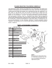
UNPACKING
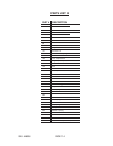
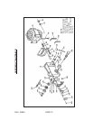
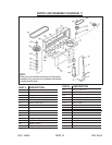
When unpacking, check to make sure all parts shown on the Parts Lists (pages 13
through 16) are included. If any parts are missing or broken, please call Harbor
Freight Tools at the number shown on the cover of this manual as soon as possible.
OPERATING INSTRUCTIONS
NOTE: For additional references to the parts listed below, refer to pages 13
through 16 of this manual.
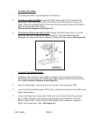
To Assemble The Drill Press:
1.
To attach the Column Support (part #3A) to the Base (part #4A)
, use the four
Hex Head Screws (part #5A) provided. (See Assembly Diagram A.)
2.
To attach the Table (part #9A) to the Drill Press
, insert the collar of the Table
(located on the underneath) into the Table Support (part #10A). Then, lock the Table
in place, using the Hex Head Screw (part 8A) and the Hex Head Socket Screw
(part 17A). (See Assembly Diagram A.)