


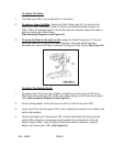
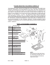
To Adjust The Table:
1. The Table (part #9A) may be adjusted in 4 directions.
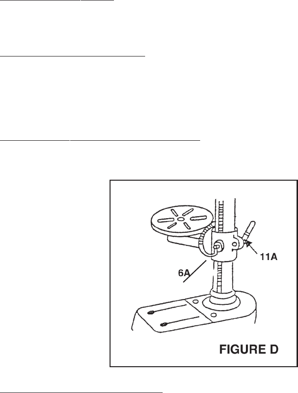
2.
To raise or lower the Table
, release the Table Clamp (part #11A), and turn the
Crank (part #6A) clockwise to raise the Table and counterclockwise to lower the
Table. When the desired height of the Table has been reached, secure the Table in
place by locking the Table Clamp.
(See Assembly Diagram A and Figure D.)
3.
To move the Table to the right or left
, release the Table Clamp (part #11A) and
move the Table left or right to the desired position. Once the desired position
has been set, secure the Table in place by locking the Table Clamp. (See Figure D.)
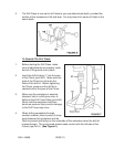
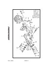
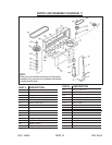
To Adjust The Spindle Depth:
1. Located on the Hub Pinion (part #18B) is a Depth Lock Screw (part #14B) and a
Depth Stop Ring w/Scale (part #15B), with depth settings in both inches and metric
units. (See Assembly Diagram B and Figure E.)
2. To set a drilling depth, insert and secure a drill bit in the Chuck (part #8C).
3. Lower the drill bit (with the power OFF) until it contacts the material to be drilled, and
hold in that position.
4. Loosen the Depth Lock Screw (part 14B), and turn the Depth Stop Ring w/Scale
(part #15B) so that the measurement for the depth of hole desired is in line the
Stop Pin (part #19B). Lock the Depth Stop Ring w/Scale in position, using the
Depth Lock Screw (part 14B). (See Figure E.)
SKU 44836 PAGE 9