


SKU 44836 PAGE 6
3.
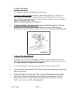
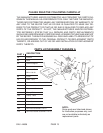
To attach the Head Assembly (part #1B) to the Column (part #1A)
, loosen
the Hex Screws (part #13B) to ensure the Screws do not protrude internally in the
Column (part #1A), as this would prevent the Head Assembly from sliding downward
fully onto the Column. With assistance raise the Head Assembly and slide it fully
onto the Column, aligning the Head Assembly with the Base (part #4A). Lock the
Head Assembly in place by tightening the Hex Screws (part #13B).
(See Assembly Diagrams A and B.)
4.
To attach the Knobs (part #16B) and Rods (part #17B) onto the Hub Assembly
(part #18B)
, screw the three Knobs onto the three Rods. Then, screw the three
Rods into the Hub Assembly. (See Assembly Diagram B.)
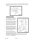
5.
To attach the Chuck (part #8C)
, attach the Table Crank (part #6A) to the Table
Support (part #10A). Raise the Table (part #9A) up the Column (part #1A) to within
6” of the Tube Quill (part #10C). Open the jaws of the Chuck (part #8C), using the
Key Chuck (part #9C). Place a piece of scrap wood on the Table to protect the nose
of the Chuck. Insert the Spindle Shaft (part #7C)-which includes Drill Chuck Arbor
(part 30C), firmly into the end of the Chuck.
Insert the other end of the Spindle Shaft into the Tube Quill, and turn the Spindle
Shaft until the prong on the Spindle Shaft aligns with the slot in the Tube Quill.
Lower the Spindle Shaft, and press the nose of the Chuck firmly down onto the
scrap wood on the Table until the Chuck is securely seated.
(See Assembly Diagrams A and C.)
To Attach The Remaining Handle:
1.
To attach the Knob (part #1C) to the Pulley Guard (part #5C)
, use the Pan Head
Screw (part #2C) provided. (See Assembly Diagram C.)
To Mount The Drill Press On A Workbench:
1. When in use, the Drill Press should be securely mounted to a flat, level, sturdy
workbench capable of supporting the weight of the Drill Press, accessories, and the
material being drilled.
2. The Base (part #4A) of the Drill Press features four 1/2” mounting holes.
(See Assembly Diagram A.)
3. With assistance, set the Drill Press in the desired position on the workbench.
4. Using the mounting holes on the Base (part #4A) as a template, mark the 1/2” holes
to be drilled through the top of the workbench.
5. With assistance, set the Drill Press aside.
6. Use a 1/2” drill bit to drill the four holes through the workbench. Reposition the Drill
Press on the workbench and secure the Drill Press to the workbench, using four 1/2”
REV 04/04