


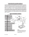
Bolts of appropriate length, Washers and Locknuts (not provided).
To Install/Reposition The Drive Belts:
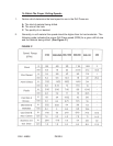
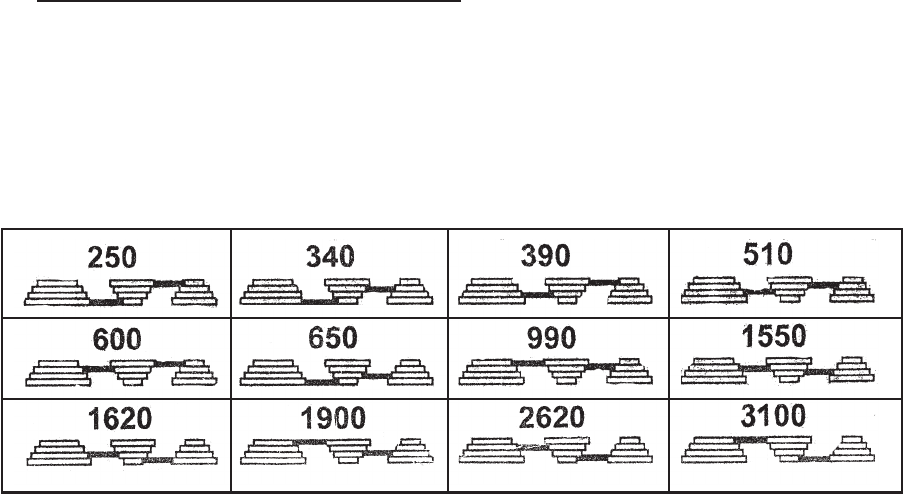
1. The Drill Press features
12
speed selections from which to choose.
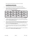
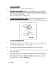
2. The two V-Belts (parts #21C, 26C), when positioned on the three Pulleys
(parts #3C, 28C, 19C), will determine the speed at which the Drill Press will run.
(See Assembly Diagram C and Figure B.)
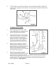
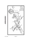
3. To install or reposition the two V-Belts (parts #21C, 26C), release the two Motor
Adjusting Knobs (part #12B) which are located on both sides of the Head Assembly
(part #1B). (See Assembly Diagram B.)
4. Lubricate the Idler Pivot Shaft (part #29C) and Center Pulley (part #28C) with a light
grease, and install the Pivot Shaft in the hole located between the Motor Pulley
(part #3C) and Spindle Pulley (part #19C). Then, insert the Center Pulley onto the
Idler Pivot Shaft. (See Assembly Diagram C.)
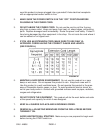
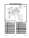
5. Consult the
Chart
inside the Pulley Guard (part #5C) or refer to Figure B, and install
the V-Belts (parts #21C, 26C) in the positions corresponding to the drill speed
desired.
6. Secure the V-Belts (parts #21C, 26C) in position by locking the two Motor Adjusting
Knobs (part #12B). (See Assembly Diagrams B and C.)
SKU 44836 PAGE 7
SPINDLE SPEED IN R. R. M.
FIGURE B
REV 12/06