


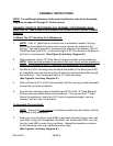
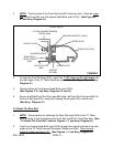
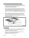

3. NOTE: The back side of the Front Rail (part #7H) has two slots. Slide the upper
slot of the Front Rail over the Square Head Bolts (part #10H). (See Figures F,
G, and Assy. Diagram H.)
10” TABLE SAW/EXTENSION
TABLES (#5H)
HEX NUT (#13H)
WASHER (#12H)
SEMI-CIRCLE
HEAD SCREW
(#2E)
SWITCH PLATE
(#3E)
SQUARE
NUT(#4E)
(LOWER SLOT)
FRONT RAIL (#7H)
(UPPER SLOT)
SQUARE HEAD BOLT (#10H)
(FRONT EDGE)
FIGURE G
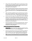
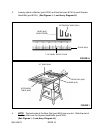
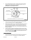
4. To align the Front Rail (part #7H), match the 7-1/8" mark on the right scale with
the right edge of the 10" Table Saw Base (part #1G). (See Figure H, and Assy.
Diagram H.)
5. Wrench tighten all five Square Head Bolts (part #10H).
(See Figures F, G, and Assy. Diagrams G, and H.)
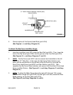
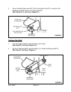
6. Secure the Right/Front End Cap (part #8H) and Left/Front End Cap (part #9H) to
the Front Rail (part #7H), using one Tapping Screw (part #1H) on each end.
(See Assy. Diagram H.)
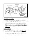
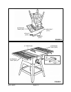
1. NOTE: The procedure for attaching the Rear Rail (part #3H) to the 10" Table
Saw is similar to that of attaching the Front Rail (part#7H) to the Table Saw. (See
“To Attach The Front Rail” section, Figures I, J, and Assy. Diagram H.)
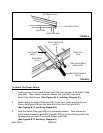
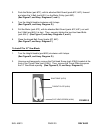
2. Insert five Square Head Bolts (part #10H) through the mounting holes in the rear
edges of the 10" Table Saw and Extension Tables (part #5H). Allow the bolt
heads to extend out about 1/2". (See Figures I, J, and Assy. Diagram H.)
SKU 46813 PAGE 13
To Attach The Rear Rail: