


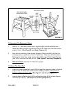
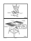
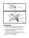
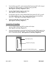

RIP FENCE (#10C)
LOCK BLOCK (#7C)
REAR RAIL (#3H)
SAW TABLE
FIGURE K
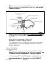
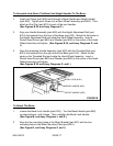
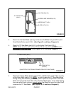
SCALE INDICATOR
(#20C)
RIP FENCE
(#10C)
FRONT RAIL
(#7H)
FINE ADJUSTMENT
KNOB (#30C)
SAW TABLE
(#17H)
RIP FENCE HANDLE
(#37C)
FIGURE L
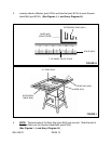
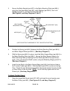
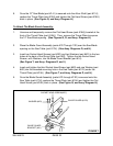
To Attach The Power Switch:
1. Insert two Semi-Circle Head Screws (part #2E) from the rear of the Switch Plate
(part #3E). Then, loosely screw one Square Nut (part #4E) onto each
Semi-Circle Head Screw. (See Figures B, G, and Assy. Diagram E.)
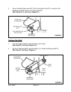
2. While holding the Switch Plate (part #3E) to the front, insert and slide the two
Square Nuts (part #4E) into the lower slot of the Front Rail (part #7H).
(See Figures B, G, and Assy. Diagram E.)
3. Slide the Switch Plate (part #3E) to a convenient position. Then, secure the
entire Switch Assembly (parts #1E through #12E) to the Front Rail (part #7H) by
tightening the two Semi-Circle Head Screws (part #2E).
(See Figures B, G, and Assy. Diagram E.)
SKU 46813 PAGE 16