


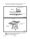

3. Secure the Motor Bracket (part #7F) to the Motor Mounting Plate (part #50-I),
using four Hex Head Bolts (part #9-I), eight Washers (part #52-I), four Lock
Washers (part #1-I), and four Hex Nuts (part #51-I).
(See Figure N, and Assy. Diagrams F, and I.)
LOCK
WASHER
(#1-I)
HEX NUT
(#51-I)
WASHER
(#52-I)
HEX HEAD BOLT (#9-I)
BELT GUARD
MOUNTING SCREW
MOTOR (#7F)
MOTOR MOUNTING PLATE
(#50-I)
(USE TWO SETS OF HARDWARE AT TOP, TWO SETS AT BOTTOM.)
FIGURE N
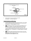
4. Position the Spring (part #46-I) between the Motor Mounting Plate (part #50-I)
and Motor Support Base (part #45-I). (See Assy. Diagram I.)
5. With the Spring (part #46-I) in place, insert the Motor Support Base (part #45-I) in
the Motor Mounting Plate (part #50-I). Secure the Motor Support Base to the
Motor Mounting Plate by inserting the Pivot Shaft (part #48-I) through the two
parts. Then, lock the Pivot Shaft in place, using two Retaining Rings (part #47-I).
(See Assy. Diagram I.)
6. Insert the two Rods in the Motor Support Base (part #45-I) into the two holes in
the Trunnion Cradle (part #36-I). Push the Motor (part #7F) in as far as it will go.
Then, Thread the two Set Screws (part #42-I) downward into the Trunnion Cradle
to clamp down on the two Rods. NOTE: Do not securely tighten the two Set
Screws yet. (See Assy. Diagram I.)
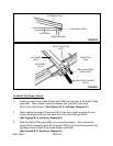
To Attach The Belt Guard:
1 Open the hinged Belt Guard (parts #1F, #4F) and insert its round opening over
the Motor Pulley (part #5F). (See Figures N, O, and Assy. Diagram F.)
SKU 46813 PAGE 18