


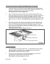

To Assemble And Attach The Bevel And Height Handles To The Base:
1. Insert one Screw (part #6G) each through a Bevel Handle and Height Handle
(part #5G). Tighten each Screw into a Hand Wheel Assembly (part #4G). Then,
attach an End Cap (part #7G) to each of the two Handles.
(See Figures B, M, and Assy. Diagram G.)
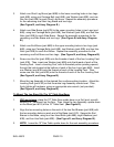
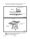
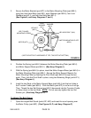
2. Align one Handle Assembly (part #4G) with the Height Adjustment Rod (part
#33-I) that extends from the front of the Base (part #1G). Match the flat spots on
the Height Adjustment Rod and inside the Hand Wheel Assembly. Insert a
Socket Head Screw (part #8G) and Washer (part #9G) in the center of the Hand
Wheel Assembly and tighten. (See Figures B, M, and Assy. Diagrams G, and
I.)
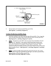
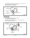
3. Align the remaining Handle Assembly (part #4G) with the Threaded Rod (part
#22-I) that extends from the right side of the Base (part #1G). Match the flat
spots on the Threaded Rod and inside the Hand Wheel Assembly. Insert a
Socket Head Screw (part #8G) and Washer (part #9G) in the center of the Hand
Wheel Assembly and tighten.
(See Figures B, M, and Assy. Diagrams G, and I.)
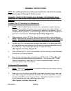
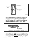
BEVEL LOCK (#19-I)
BEVEL HANDLE (#5G)
HEIGHT HANDLE (#5G)
FIGURE M
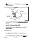
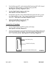
To Attach The Motor:
1. Loosen the Bevel Lock Handle (part #19-I). Turn the Bevel Handle (part #5G)
counterclockwise until it stops. Then, retighten the Bevel Lock Handle.
(See Figure M, and Assy. Diagrams I, and G.)
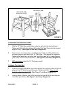
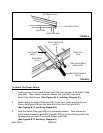
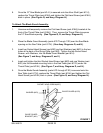
2. Align the four mounting holes in the Motor Bracket (part #7F) with the four
mounting holes in the Motor Mounting Plate (part #50-I).
(See Figure N, and Assy. Diagrams F, and I.)
SKU 46813 PAGE 17