


Page 12SKU 65345 For technical questions, please call 1-800-444-3353.
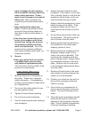
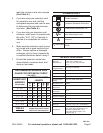
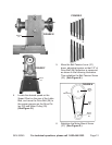
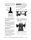
FIGURE E
BACK LID
(20)
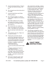
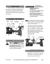
FIGURE F
SIDE LID
(63)
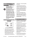
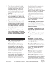
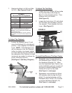
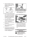
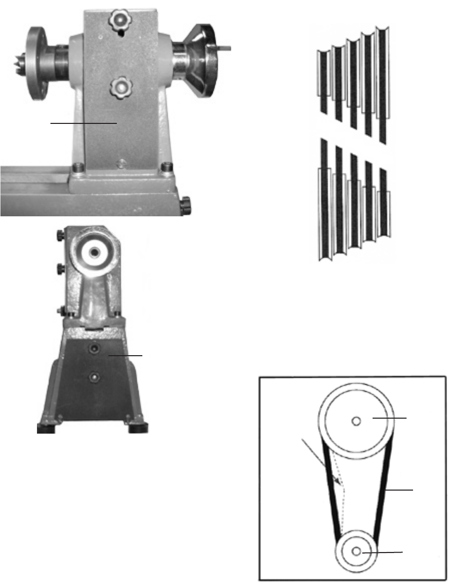
4. Locate the desired speed on the
Speed Chart on the rear of the Lathe
Bed, and move the Drive Belt (26) to
the proper grooves on the Drive Pul-
ley (25) and Motor Pulley (29).
(See Figure G.)
FIGURE G
750
1100
1600
2200
3200
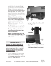
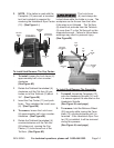
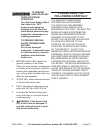
5. Move the Belt Tension Lever (31)
down, adjusting tension so that 1/2” of
Drive Belt (26) deection is measured
as shown in the following illustration.
Then retighten the Belt Tension Screw
(33). (See Figure H.)
FIGURE H
DRIVE
PULLEY
(25)
MOTOR
PULLEY
(29)
1/2”
DEFLECTION
DRIVE
BELT
(26)
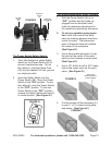
6. Retighten the Motor Mount Screw
(27). (See Figure D.)