


Page 9SKU 65345 For technical questions, please call 1-800-444-3353.
UNPACKING
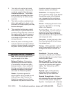
When unpacking, check to make sure
that the item is intact and undamaged. If
any parts are missing or broken, please
call Harbor Freight Tools at the number
shown on the cover of this manual as soon
as possible.
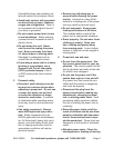
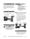
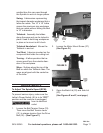
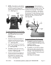
PRODUCT FEATURES
FIGURE A
BALANCE
WHEEL
(22)
BACK
LID
(20)
HEADSTOCK
SPINDLE
(14)
HEADSTOCK
SPUR
CENTER
(12)
TOOL
REST
(35)
BED
SLIDE
LID
(63)
CUP
CENTER
(11)
LOCK
LEVER
(6)
TAILSTOCK
(5)
TAILSTOCK
HANDWHEEL
(4)
SWITCH
(46)
BED
(1)
ASSEMBLY INSTRUCTIONS
Read the ENTIRE IMPORTANT
SAFETY INFORMATION section
at the beginning of this manual
including all text under
subheadings therein before set
up or use of this product.
TO PREVENT
SERIOUS INJURY
FROM ACCIDENTAL
OPERATION:
Turn the Power Switch (46) of
the Lathe to its “OFF”
position and unplug the tool
from its electrical outlet
before assembling or making
any adjustments.
Note: For additional information regarding
the parts listed in the following pages,
refer to the Assembly Diagram near
the end of this manual.
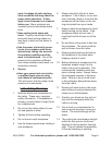
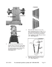
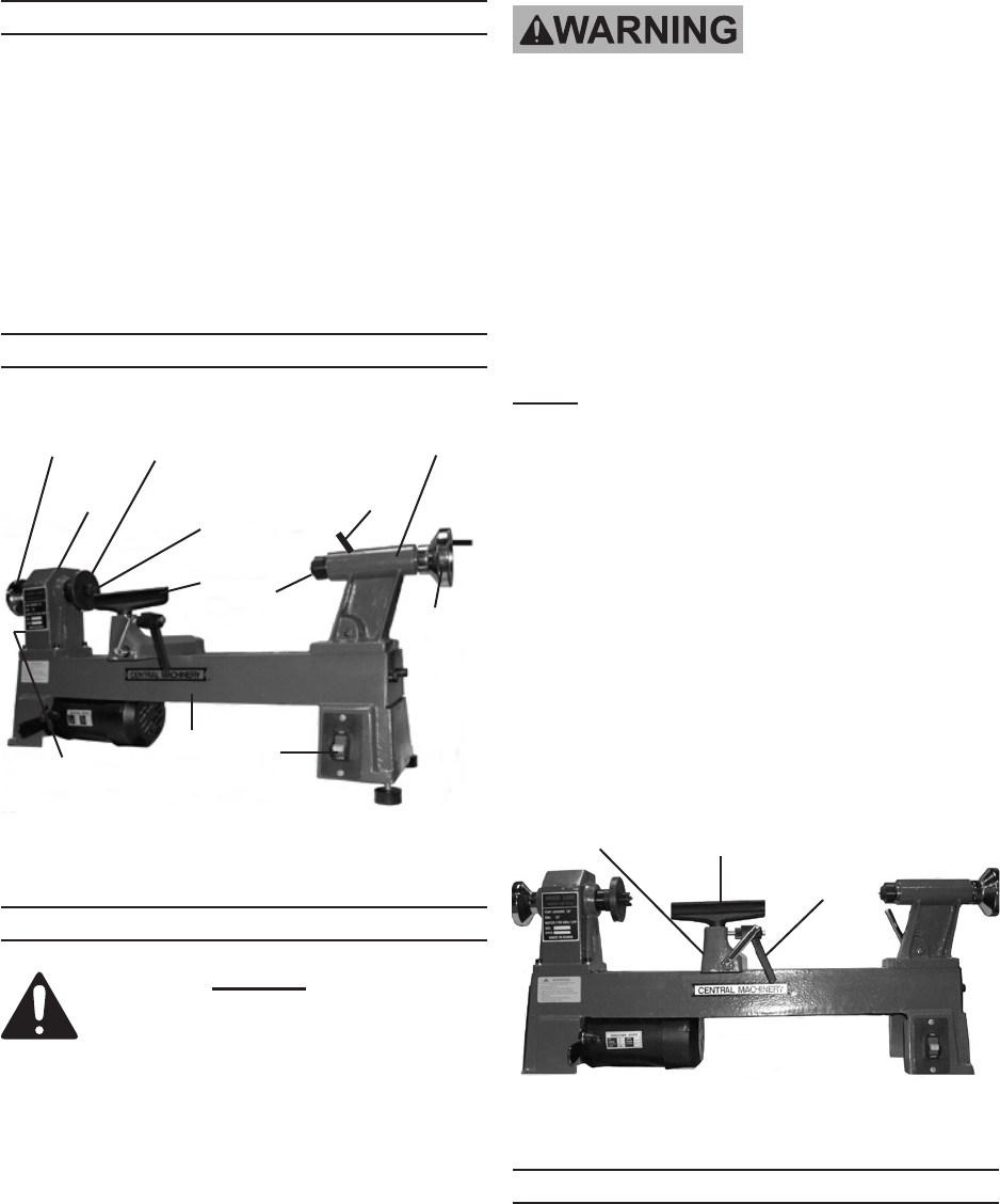
The Lathe comes fully assembled 1.
with the exception of the Tool Rest
(35). To install the Tool Rest, loosen
the Lock Lever (41). Insert the Tool
Rest into the Tool Rest Base (36).
Then retighten the Lock Lever to se-
cure the Tool Rest in place.
(See Figure B.)
FIGURE B
LOCK LEVER
(41)
TOOL REST
(35)
TOOL REST
BASE
(36)
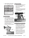
WORK AREA SET UP
Designate a work area that is clean 1.
and well-lit. The work area must not
allow access by children or pets to
prevent injury and distraction.