


Page 14SKU 65345 For technical questions, please call 1-800-444-3353.
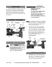
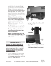
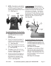
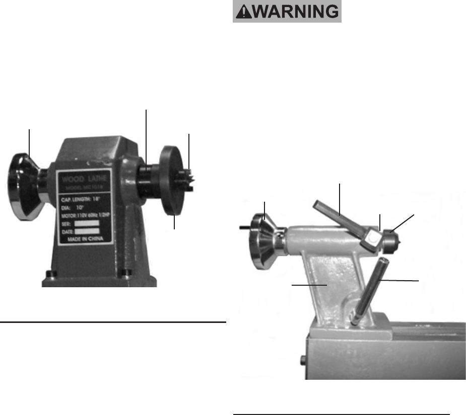
NOTE: 3. If the Lathe is used with the
Faceplate (13) removed, a knockout
tool (not included) is required for
removing the Headstock Spur Center
(12). (See Figure L.)
FIGURE L
HEADSTOCK
SPUR CENTER
(12)
FACEPLATE
(13)
HEADSTOCK
SPINDLE
(14)
BALANCE
WHEEL
(22)
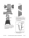
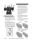
To Install And Remove The Cup Center:
To install1. , loosen the Lock Lever (6)
approximately half a turn counter-
clockwise.
(See Figure M.)
Rotate the Tailstock Handwheel (4) 2.
clockwise until the Tail Axis (8) pro-
trudes out of the Tailstock (5) about
3/4”. (See Figure M.)
Insert the Cup Center (11) and push 3.
rmly. Then retighten the Lock Lever
(6). (See Figure M.)
To remove4. , loosen the Lock Lever
(6) approximately half a turn counter-
clockwise. (See Figure M.)
Rotate the Tailstock Handwheel (4) 5.
counterclockwise until the Tail Axis
(8) bottoms out, causing the Cup
Center (11) to be forced out of the
Tail Axis. (See Figure M.)
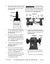
The Lock Lever
(6) must always be
locked down while the Lathe is in use. The
workpiece can be thrown from the Lathe
if this step is not followed. The Tail Axis
(8) should not protrude from the Tailstock
(5) more than 2” or the Tail Axis will not be
supported enough. Failure to follow these
warnings may result in personal injury.
(See Figure M.)
FIGURE M
RELEASE
LEVER
(7)
TAILSTOCK
(5)
LOCK
LEVER
(6)
TAILSTOCK
HAND WHEEL
(4)
TAIL
AXIS
(8)
CUP
CENTER
(11)
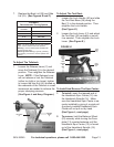
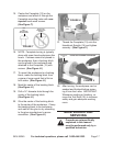
To Install And Remove The Faceplate:
To install1. , thread the Faceplate (13)
onto the Headstock Spindle (14) until
it is secure against the shoulder on the
Headstock Spindle.
(See Figure N, next page.)
To remove2. , hold the Balance Wheel
(22) securely while turning the Face-
plate (13) counterclockwise until it is
removed. If the Headstock Spur Cen-
ter (12) is installed, it will be removed
during this process.
(See Figure N, next page.)