


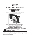

SKU 67026 For technical questions, please call 1-800-444-3353. Page 10
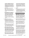
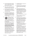
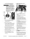
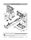
BLADE MOUNTING/REMOVAL:1.
TO PREVENT
SERIOUS INJURY
FROM FLYING FRAGMENTS:
Do not use blades made from
high-speed steel, abrasive
blades, or metal- or masonry-
cutting blades. The guards of
this saw are not designed to
protect against the failure of
such blades.
Blade
Bolt
Blade Spindle
Lock
Outer
Flange
Inner
Flange
a. -
moving the Blade Bolt, turning it
counterclockwise.
b.
Hold open the Moveable Guard and c.
comes off, place it on the spindle
Install the new blade, with the direc-d.
tional arrow on the blade pointing
the same as the directional arrow on
the stationary guard.
Place the Outer Flange on the spin-e.
-f.
installing the Blade Bolt, turning it
clockwise.
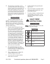
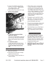
BEVEL ADJUSTMENT AND 0° 2.
BEVEL STOP:
Base
Plate
Bevel
Scale
Bevel
Knob
Fence
Bolt
Fence
Bolt
Bevel Stop
Bolt
Bevel
Mark
FIGURE 2
a. To read the approximate blade
bevel:
Compare the Bevel Mark with the
Bevel Scale.
To set the 0° bevel stop:b.
the right side of the Base Plate up
as far as possible. The Bevel Mark
should line up with the 0 line on the
bevel scale.
If it is higher than the mark, turn the
Bevel Stop Bolt counterclockwise.
If it is lower than the mark, loosen
the Nut on the Bevel Stop Bolt and
turn the Bolt clockwise.
After it is aligned, tighten the Nut on
the Bevel Stop Bolt.
To adjust the bevel: c.
the Base Plate to the desired bevel.
Tighten the Bevel Knob before
use.
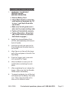
RIP FENCE INSTALLATION / AD-3.
JUSTMENT:
a.
Figure 2) and insert the Rip Fence
(not shown in Figure 2, see Assem-
bly Diagram) into the two brackets
on the Base Plate from the left.