


SKU 94355 For technical questions, please call 1-800-444-3353 PAGE 9
UNPACKING
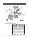
When unpacking, check to make sure all the parts shown on the Parts List on page 14
are included. If any parts are missing or broken, please call Harbor Freight Tools at the
number shown on the cover of this manual as soon as possible.
ASSEMBLY INSTRUCTIONS
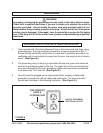
1. CAUTION! Always make sure the Pressure Switch (57) of the Air
Compressor is in its “OFF” position and the unit is unplugged from its electrical
outlet prior to performing any assembly on this unit.
2. To attach the Handle (9) to the Air Compressor, align the four mounting holes in
the Handle with the four
threaded
mounting holes located at the rear of the unit.
Then secure the Handle in place with four Screws (7). (See Page 16)
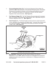
3. Slide the Quick Coupler (11) towards the compressor body and insert the Air
Hose (71) to the Quick Coupler (11). (See Page 16)
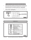
AIR COMPRESSOR CONTROLS
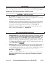
1. Pressure Switch (57): The Pressure Switch turns the Air Compressor on and
off. When in the “ON” position, the Pressure Switch allows the Compressor to
automatically adjust to its “run” stage when the air pressure inside the Air Tank
(3) falls below 85 PSI. The Pressure Switch also automatically turns the Com
pressor to its “idle” stage when the air pressure inside the Air Tank reaches 125
PSI. Always keep the Pressure Switch in its “OFF” position when the unit is not
in use. (See Figure D, next page.)
2. Safety Valve (10): If the Pressure Switch (57) does not shut down the Motor of
the Air Compressor when the pressure reaches 125 PSI, the Safety Valve will
automatically pop open to prevent over-pressurization. To operate manually, pull
the ring on the Safety Valve to relieve air pressure in the Air Tank (3).
(See Figure D, next page.)
3. Tank Pressure Gauge (13): The Tank Pressure Gauge measures the pressure
level of the air stored in the Air Tank (3), and is not adjustable by the operator.
(See Figure D.)